Crimp connector and manufacturing method thereof

A manufacturing method and connector technology, which is applied in the direction of contact manufacturing, welding/welding connection, connection, etc., can solve problems such as the relative position of the flat plate part on the difficult upper side, the size deviation of the spiral structure, and the mutual opening of the spring parts.

Active Publication Date: 2020-02-07
ALPS ALPINE CO LTD
View PDF4 Cites 0 Cited by
  • Summary
  • Abstract
  • Description
  • Claims
  • Application Information

AI Technical Summary

Problems solved by technology

[0008] In the crimp connector described in Patent Document 1, the first spring part and the second spring part are bent independently of each other from the lower flat plate part, so it is difficult to ensure high precision due to springback after deformation of each spring part. The relative position of the upper side flat part and the auxiliary upper side flat part
Therefore, variations in the size of the helical structure are likely to occur, and it is difficult to minimize the variation in elastic resilience during compression for each crimp connector.
In addition, since the first spring part and the second spring part do not constrain each other, there is a possibility that the crimp connector may be inappropriately acted accidentally during the process of storing the crimp connector or in the process of mounting the crimp connector to an electronic device or the like. When an external force is applied, there is a possibility of deformation such as opening of each spring part

Method used


Image

  • Crimp connector and manufacturing method thereof
  • Crimp connector and manufacturing method thereof
  • Crimp connector and manufacturing method thereof

Examples


Embodiment Construction

[0044] The crimp connector 1 according to the embodiment of the present invention is formed by bending a conductive metal plate by press working. The metal plate is copper or a copper alloy, and is formed of Corson alloy (Cu—Ni—Si alloy) in the embodiment.

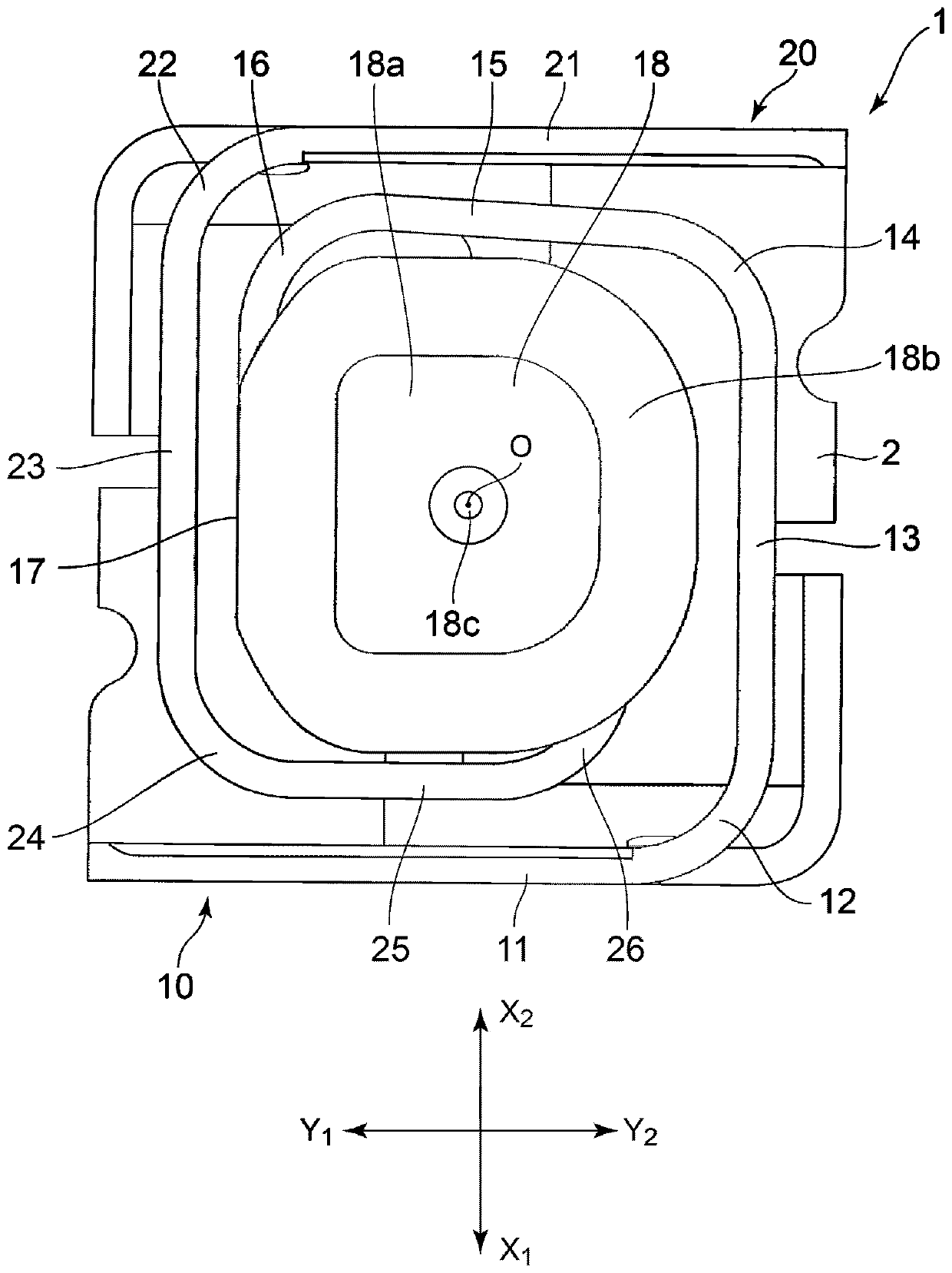
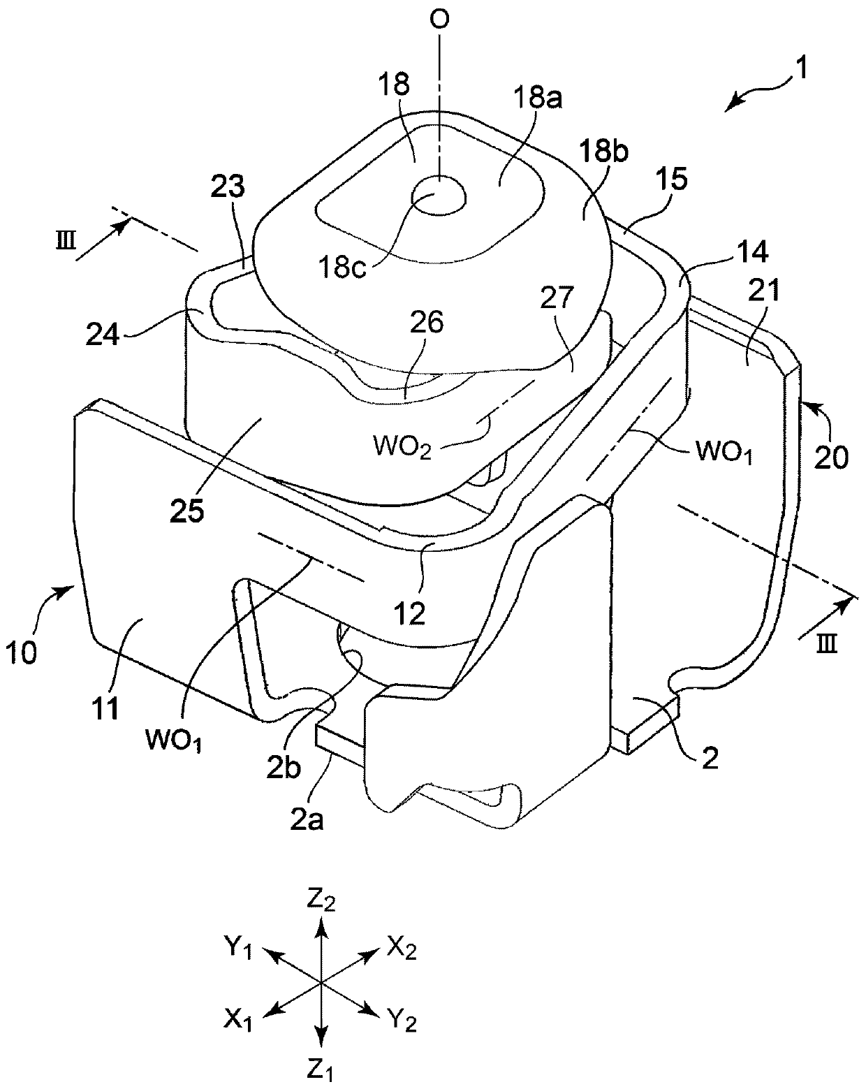
[0045] Crimp Connector 1's figure 1 The dimensions of the X-direction and the Y-direction in the shown planar shape are respectively 2 mm × 2 mm or less, preferably 1.5 mm × 1.5 mm or less. figure 2 The height dimension in the Z direction in the free state with no load applied is 1.5 mm or less, preferably about 1 mm.

[0046] This crimp connector 1 is used for a connection between circuit boards, a connection between a circuit board and an electronic component such as an IC, or a circuit board and a wiring cable (flexible wiring cable) by mounting a plurality of them on a circuit board. the connection part, etc.

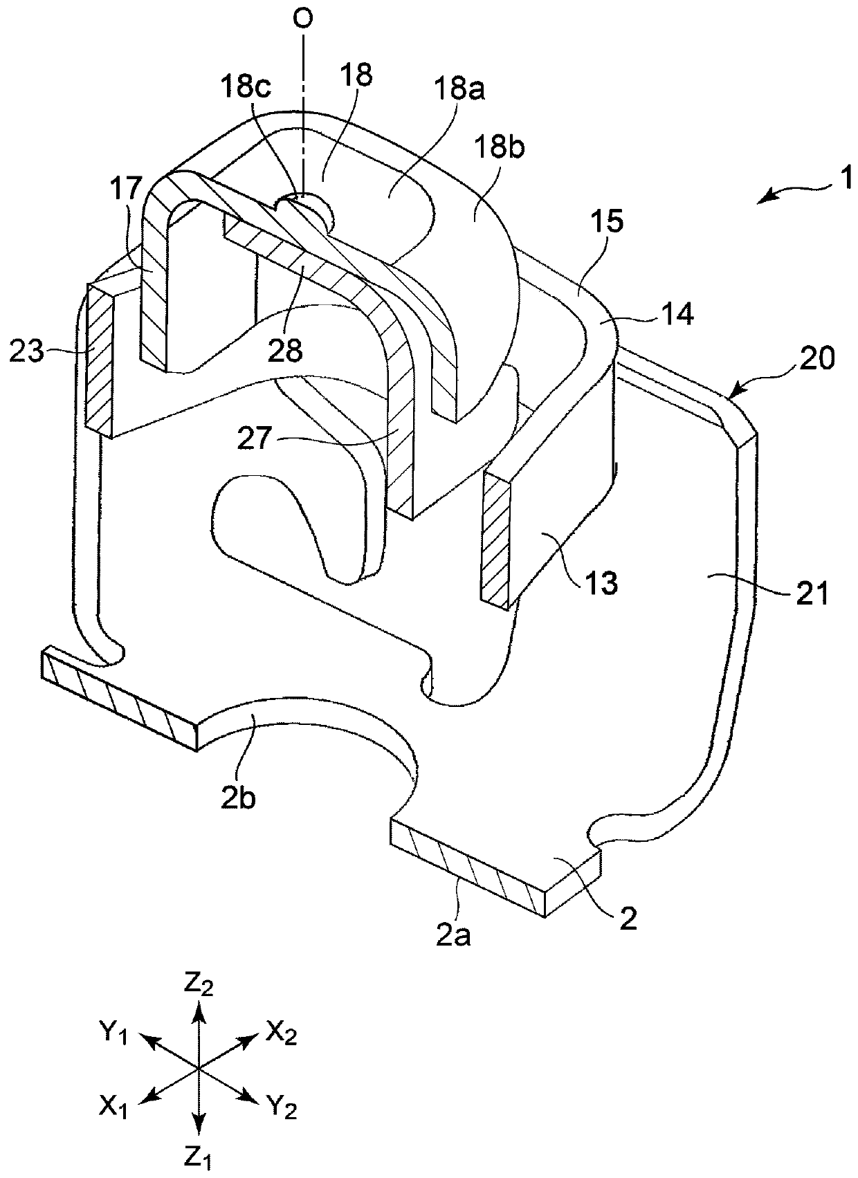
[0047] exist figure 2 and image 3 shows the crimp connector 1 in a free state with no load applied. ...


PUM


Abstract

PROBLEM TO BE SOLVED: To provide a pressure welding connector capable of stabilizing dimension accuracy of a spiral structure part that consists of two spiral parts, and also improving a strength of the spiral structure part, and a manufacturing method thereof.SOLUTION: A spiral structure part is formed from a conductive plate. The spiral structure part includes a first spiral part 10 and a second spiral part 20. A contact part 18 is formed in a tip of the first spiral part 10, and a support part 28 facing the contact part 18 from a base part side is formed in a tip of the second spiral part 20. The contact part 18 and the support part 28 are welded and fixed, such that the first spiral part 10 and the second spiral part 20 are coupled while keeping relative positions high.SELECTED DRAWING: Figure 3

Description

technical field [0001] The present invention relates to a crimp connector in which a helical structure is formed from a conductive plate material, and more particularly to a crimp connector with a structure capable of exhibiting stable elastic resilience and easily preventing deformation of the helical structure, and a method for manufacturing the same. Background technique [0002] Patent Document 1 describes a crimp connector formed of a conductive sheet material. [0003] The crimp connector has a lower flat plate, an upper flat plate, and an auxiliary upper flat plate located below the upper flat plate. A first spring portion is provided between the lower flat plate portion and the upper flat plate portion, and a second spring portion is provided between the lower flat plate portion and the auxiliary upper flat plate portion. Both the first spring portion and the second spring portion are bent so as to rise from the lower flat plate portion to form a helical shape, and ...

Claims


Application Information

Patent Timeline
Patent Type & Authority Patents(China)
IPC IPC(8): H01R12/71H01R13/24H01R4/02H01R43/02H01R43/16
CPCH01R4/029H01R12/718H01R13/2414H01R43/0221H01R43/16H01R13/24
Inventor 村山丈刚佐藤一树前田征宣佐野浩典
Owner ALPS ALPINE CO LTD
Why Eureka
Try Eureka