A test device and installation method for precise positioning of propeller front compensation conduit

A test device and precise positioning technology, used in transportation and packaging, ship construction, ship design, etc., can solve the problems of lifting the model out of the ship pool, ineffectiveness, installation deviation, etc., and achieve the effect of avoiding manual errors

Active Publication Date: 2019-03-22
708TH RES INST OF CSSC
View PDF6 Cites 0 Cited by
  • Summary
  • Abstract
  • Description
  • Claims
  • Application Information

AI Technical Summary

Problems solved by technology

First of all, it is difficult to grasp the longitudinal, transverse and vertical positions of the compensation duct on the ship model; secondly, the α angle formed by the compensation duct’s rotation around its own vertical z-axis and the vertical plane and the angle formed by the compensation duct’s rotation around its own transverse y-axis and the horizontal plane The β angle is even more difficult; again, during the test, it is often necessary to adjust the α and β angles to confirm the energy-saving solution
Changing the angle after stripping the compensating conduit from the boat model not only requires hoisting the model out of the boat tank, wasting time but also not getting the final effect
[0003] In the model test after the installation of the compensation duct, the accurate test of the thrust and torque of the propeller directly determines whether the energy saving is effective. If it is done manually by a ship model master, it is easy to cause installation deviations in position and angle. After installing the compensation duct Whether it is energy-saving or not, it is difficult to determine

Method used


Image

  • A test device and installation method for precise positioning of propeller front compensation conduit
  • A test device and installation method for precise positioning of propeller front compensation conduit

Examples


Embodiment Construction

[0025] The present invention will be further described below in conjunction with the accompanying drawings and specific embodiments, but not as a limitation of the present invention.

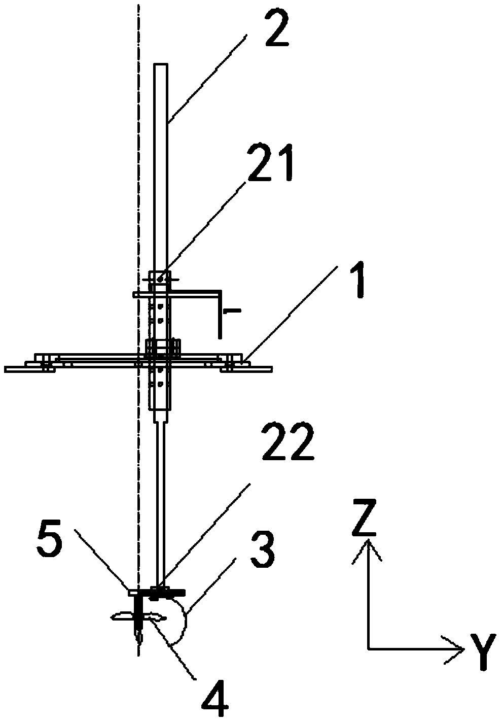
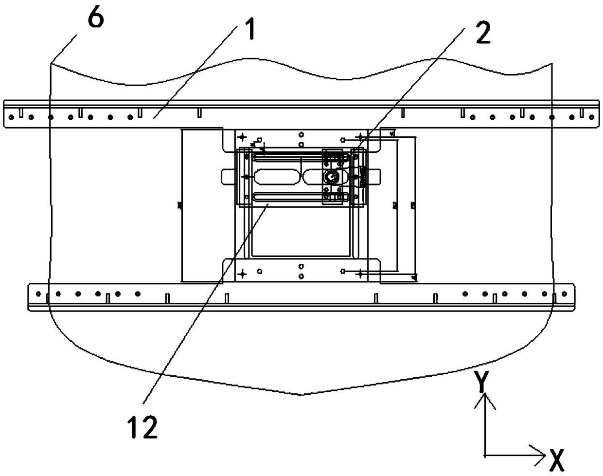
[0026] figure 1 It is a front view of a test device for accurate positioning of the paddle front compensation guide of the present invention. figure 2 It is a top view of a test device for accurate positioning of the paddle front compensation guide of the present invention.

[0027] XYZ axis coordinate system please refer to figure 1 and figure 2 Shown:

[0028] See Figure 1 to Figure 2 As shown, in a preferred embodiment, a test device for accurate positioning of the compensation conduit in front of the paddle is characterized in that it includes:

[0029] XYZ locating frame 1, XYZ locating frame 1 is installed on the surface of hull, and XYZ locating frame 1 is positioned at the top of the position in front of the paddle of hull; A through hole is offered behind the hull stern; XYZ loc...


PUM


Abstract

The invention discloses a testing device for precisely positioning a compensation guide pipe in front of a propeller. An XYZ positioning rack is arranged on the surface of a hull; a through hole is formed in the tail of the hull; a positioning rack bottom surface is arranged on the XYZ positioning rack and moves in the X axis or Y axis direction through a plurality of sliding blocks; the upper endof a guide pipe connection rod penetrates through the through hole of the hull and is connected with the positioning rack bottom surface, and the guide pipe connection rod can move up and down in theZ-axis direction; a first flange is arranged at the upper end of the guide pipe connection rod; the lower end of the compensation guide pipe is connected to the lower end of the guide pipe connectionrod through a second flange; the second flange adjusts the trim angle beta of the compensation guide pipe; an angle indicator displays the circumferential rotation angle alpha of the guide pipe connection rod; a ruler is used for detecting the zero-degree positions of alpha and beta of the compensation guide pipe. According to a device and method for precisely positioning and mounting the compensation guide pipe, the manual errors of ship model machining workers during mounting are avoided, and the stress of the propeller after the compensation guide pipe is mounted can also be accurately measured.

Description

technical field [0001] The invention relates to the technical field of ship measurement, in particular to the technical field of a test device for precise positioning of a propeller front compensation conduit. Background technique [0002] Installing compensating ducts is an important measure for ship energy saving. During the actual model test, the installation of the compensation conduit was done manually by the ship model processing master. First of all, it is difficult to grasp the longitudinal, transverse and vertical positions of the compensation duct on the ship model; secondly, the α angle formed by the compensation duct’s rotation around its own vertical z-axis and the vertical plane and the angle formed by the compensation duct’s rotation around its own transverse y-axis and the horizontal plane The β angle is even more difficult; again, during the test, it is often necessary to adjust the α and β angles to confirm the energy-saving solution. Changing the angle a...

Claims


Application Information

Patent Timeline
Patent Type & Authority Patents(China)
IPC IPC(8): B63B9/00
CPCB63B71/00
Inventor 刘小健吴永顺陈禧陈红梅王海波
Owner 708TH RES INST OF CSSC
Why Eureka
Try Eureka