
Camera driving mechanism for SMT printing machine

A camera-driven, printing press technology, applied in the direction of supporting machines, mechanical equipment, machines/brackets, etc., can solve problems such as affecting the shooting accuracy of the camera, unable to ensure the synchronous movement of the fixed plate of the camera, unable to realize the synchronous movement of the camera, etc. The effect of shooting precision

Pending Publication Date: 2018-06-08
浙江华企正邦自动化科技有限公司
View PDF7 Cites 2 Cited by
  • Summary
  • Abstract
  • Description
  • Claims
  • Application Information

AI Technical Summary

Problems solved by technology

In order to improve the synchronization accuracy of camera fixed plate movement in the industry, the system usually reserves some time after the nut stops moving on the screw, so that the other end of the camera fixed plate can keep up with the displacement position of the camera fixed plate as much as possible through inertial sliding. , but there is no guarantee that the two ends of the camera fixing plate can move synchronously, that is, the camera cannot move synchronously on the Y axis, which will affect the shooting accuracy of the camera

Method used


Image

  • Camera driving mechanism for SMT printing machine
  • Camera driving mechanism for SMT printing machine

Examples


Embodiment Construction

[0023] The present invention will be further described below in conjunction with the accompanying drawings.

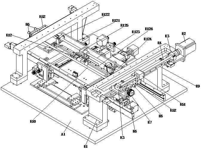
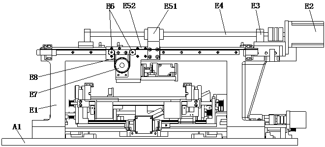
[0024] Such as Figure 1 to Figure 2 As shown, a camera driving mechanism of an SMT printing machine according to the present invention includes a frame platform A1, a camera fixing plate E121, an X-axis power assembly, a Y-axis power assembly, and a camera E12, and the surface of the frame platform A1 is arranged There are two Y-axis beams E1 parallel to each other. The X-axis power assembly is fixed on the camera fixing plate E121, and the X-axis power assembly drives the camera E12 to move along the X-axis direction.

[0025] It also includes a linkage shaft E10, the Y-axis beam E1 is provided with a Y-axis linkage mechanism, two Y-axis linkage mechanisms are arranged in parallel to each other, and the two Y-axis linkage mechanisms are connected through the linkage shaft E10; the Y-axis power The assembly is arranged on the first Y-axis beam E1, and the Y-axis powe...


PUM


Abstract

The invention relates to the technical field of camera movement of SMT printing machines and particularly relates to a camera driving mechanism for an SMT printing machine. The camera driving mechanism comprises a linkage shaft, wherein two Y-axis crossbeams are arranged on the surface of a stander platform, and an X-axis power assembly is fixedly arranged on a camera fixing plate and is used fordriving a camera to move along the X-axis direction; the Y-axis crossbeams are provided with Y-axis linkage mechanisms, and the two Y-axis linkage mechanisms are connected through the linkage shaft; aY-axis power assembly is connected with the Y-axis linkage mechanism in the first Y-axis crossbeam; two ends of the camera fixing plate are respectively fixedly connected with the two Y-axis linkagemechanisms; and the Y-axis power assembly is used for driving the camera fixing plate to move along the Y-axis direction through the Y-axis linkage mechanism. By utilizing the Y-axis linkage mechanisms during the use of the camera driving mechanism, two ends of the camera fixing plate can synchronously move along the Y-axis direction in real time, and any one end of the camera fixing plate does not lag, so that the photographing precision of a camera is guaranteed.

Description

technical field [0001] The invention relates to the technical field of camera movement of an SMT printing machine, in particular to a camera driving mechanism of an SMT printing machine. Background technique [0002] The camera of the SMT printing machine is usually set on the camera fixing plate. One end of the camera fixing plate is connected to another Y-axis beam through a nut and a screw in turn, and the other end of the camera fixing plate is connected to a Y-axis beam through a slider and a guide rail in turn. Connection; that is, one end of the camera fixing plate is provided with an active driving force, and the other end of the camera fixing plate is a driven setting. Its working principle is: when the screw rotates, the nut moves along the length of the screw with the camera fixing plate, and the movement of the other end of the camera fixing plate is lagging behind the movement of one end of the camera fixing plate. In order to improve the synchronization accura...

Claims


Application Information

Patent Timeline
Patent Type & Authority Applications(China)
IPC IPC(8): F16M11/22F16M11/04F16M11/18
CPCF16M11/043F16M11/18F16M11/2085F16M11/22
Inventor 梁文灿李清国
Owner 浙江华企正邦自动化科技有限公司
Learn More