
Manufacturing method of drying device

A production method and technology of drying equipment, applied in drying, drying machines, lighting and heating equipment, etc., can solve the problems of reducing the qualified rate of finished sheet metal parts, increasing the workload of personnel, and poor use effects, etc., to achieve Reduce the risk, improve the maintenance effect, and expand the effect of drying range

Pending Publication Date: 2018-06-08
TIANJIN POLYART VACUUM PLATING
View PDF5 Cites 0 Cited by
  • Summary
  • Abstract
  • Description
  • Claims
  • Application Information

AI Technical Summary

Problems solved by technology

[0002] At present, when drying the sheet metal parts on the production line, it is usually necessary to use drying equipment to quickly dry the sheet metal parts, but the traditional drying equipment has poor drying effect and uneven drying, thus reducing the The qualified rate of finished products of sheet metal parts
[0003] When the existing waterline drying equipment dries sheet metal parts, it can usually only dry one side of the sheet metal part, but the drying range is low and the use effect is poor. The manufacturing method of the existing drying equipment When performing maintenance, it is usually necessary for personnel to climb in person to perform maintenance, which increases the workload of personnel and is dangerous to a certain extent.

Method used


Image

  • Manufacturing method of drying device
  • Manufacturing method of drying device
  • Manufacturing method of drying device

Examples


Embodiment Construction

[0019] In order to make the technical means, creative features, goals and effects achieved by the present invention easy to understand, the present invention will be further described below in conjunction with specific embodiments.

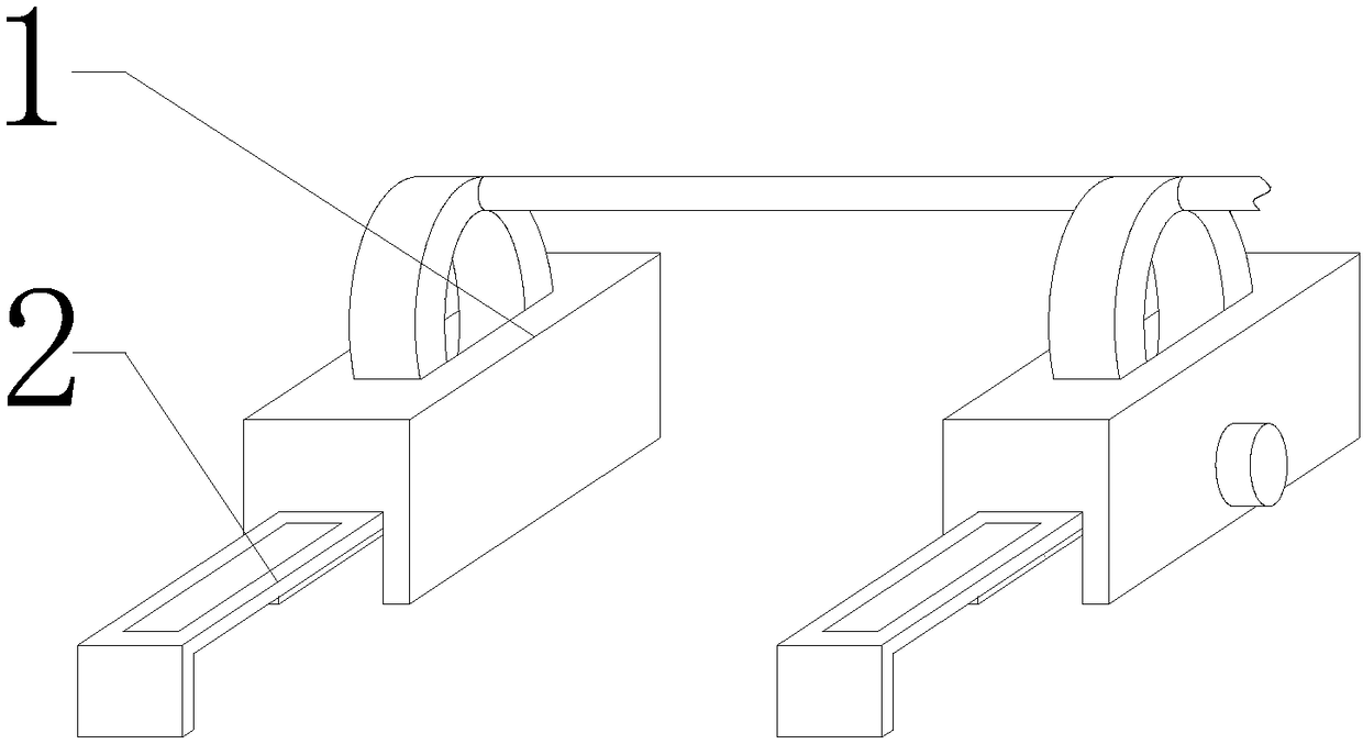
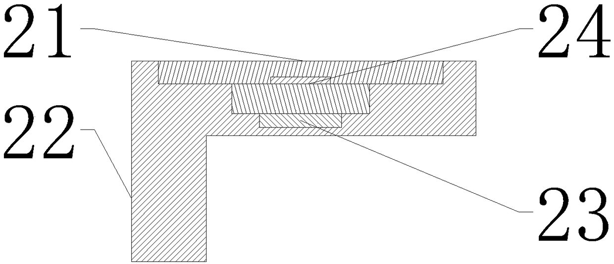
[0020] see Figure 1-Figure 3 , the present invention provides a technical solution: a method for manufacturing drying equipment, including a drying mechanism 1 and a maintenance mechanism 2, and the maintenance mechanism 2 is installed at the front end of the drying mechanism 1.

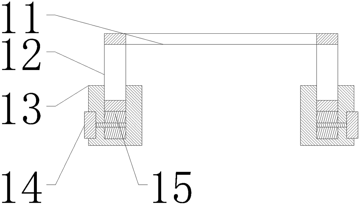
[0021] The drying mechanism 1 includes a drying pipeline 11, a gear ring 12, a base 13, a motor 14 and a circular gear 15, the drying pipeline 11 is arranged at the inner end of the gear ring 12, and a circular gear 15 is installed at the lower end of the gear ring 12. The outer end of the gear 15 is equipped with a motor 14, the circular gear 15 is arranged at the inner bottom of the base 13, the gear ring 12 is arranged on the base 13, the motor 14 is installed at the...


PUM


Abstract

The invention provides a manufacturing method of a drying device. A drying pipe, a gear ring, a bear, a motor, a circular gear, a lifting plate, a supporting plate, a rotating disc and an electric cylinder are included, the drying pipe is arranged at the inner end of the gear ring, the circular gear is installed at the lower end of the gear ring, the motor is assembled at the outer end of the circular gear, the circular gear is arranged at the bottom end inside the base, the gear ring is arranged on the base, the motor is installed at the outer end of the base, the motor penetrates through thebase to be connected with the circular gear, the gear ring and the circular gear are subjected to gear engagement, the drying range is enlarged, the electric cylinder is installed at the lower end ofthe lifting plate, the rotating disc is arranged at the lower end of the electric cylinder, the rotating disc is installed at the bottom end inside the supporting plate, and due to the design, the maintaining effect tis improved; the device is convenient to use and operate, capable of performing rotary drying, convenient to maintain, good in stability and high in reliability.

Description

technical field [0001] The invention relates to a method for manufacturing drying equipment, which belongs to the technical field of waterline drying. Background technique [0002] At present, when drying the sheet metal parts on the production line, it is usually necessary to use drying equipment to quickly dry the sheet metal parts, but the traditional drying equipment has poor drying effect and uneven drying, thus reducing the The qualified rate of finished products of sheet metal parts has been improved. [0003] When the existing waterline drying equipment dries sheet metal parts, it can usually only dry one side of the sheet metal part, but the drying range is low and the use effect is poor. The manufacturing method of the existing drying equipment When maintenance is performed, personnel are usually required to climb in person to perform maintenance, thereby increasing the workload of personnel and having certain dangers. Contents of the invention [0004] Aiming ...

Claims


Application Information

Patent Timeline
Patent Type & Authority Applications(China)
IPC IPC(8): F26B21/00F26B25/00F26B25/02
CPCF26B21/004F26B25/00F26B25/02
Inventor 李建阁阮祥辉
Owner TIANJIN POLYART VACUUM PLATING
Learn More