Feeders for liquid to pasty materials

A feeder and feeding technology, applied in a single hand-held device, spray device, etc., can solve problems such as material bridge breakage

Active Publication Date: 2021-02-09
RPC BRAMLAGE
View PDF5 Cites 0 Cited by
  • Summary
  • Abstract
  • Description
  • Claims
  • Application Information

AI Technical Summary

Problems solved by technology

During the screwing process, the original shape ring is moved downwards by the positive engagement protrusion of the original shape holder in cooperation with the feeder body and causes a breakage of the material bridge
From document WO 93 / 03857 A2 an undisturbed retainer in the form of a tear strip is known, but itself can only be torn

Method used


Image

  • Feeders for liquid to pasty materials
  • Feeders for liquid to pasty materials
  • Feeders for liquid to pasty materials

Examples


Embodiment Construction

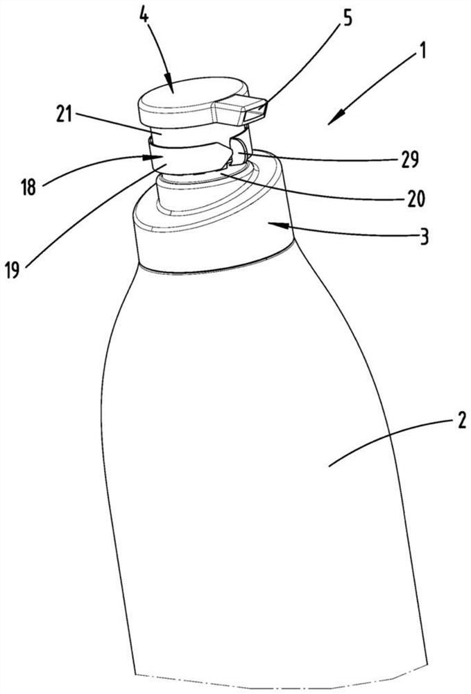
[0047]First according toFigure 1 to 16 The first embodiment of the feeder 1 for liquid to paste is shown and described.

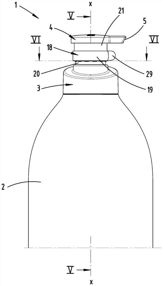
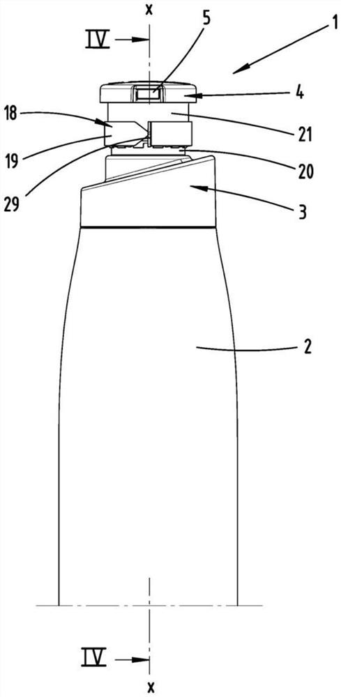
[0048]The feeder 1 has a feeder body 3 that can be basically placed, especially screwed onto the container 2, and a feeder head 4 having a feeder port 5.

[0049]In order to output the material stored in the container 2, the feeder head 4 is perpendicular to the horizontally oriented placement surface and can be moved between the moving out position and the moving in position, and the feeder 1 can be placed on the placement surface. SeeFigure 14 , The moving direction is marked as V. Thus, the movement of the pump can be realized, wherein, in the moving position of the feeder head 4, that is, in the sinking position, the material is output through the feeder port 5, and the feeder head 4 moves to the moving out position In the process, the material is sucked into the pump chamber 6 from the container 2.

[0050]The pump chamber 6 is suitably configured to flow between the...


PUM


Abstract

The present invention is a feeder (1) for liquid to pasty material, which has a feeder head (4) and a feeder body (3), wherein the material can be fed from The feeder mouth (5) of the feeder head (4) is output, and when the feeder (1) is placed on a horizontally oriented placement surface, the feeder head (4) can The direction of movement (V) of the horizontal resting surface moves between an out position and an in position to implement the movement of the pump, wherein the feeder head (4) is also relative to the feeder body (3) Can be turned so that said feeder mouth (5) moves in a horizontal plane when the feeder head (4) rotates. In order to improve the aforementioned feeder advantageously, it is proposed here that the feeder (1) has an original retainer (18), which is fixed on two opposite sides of the feeder (1). On the parts that can rotate each other, the original shape retainer (18) is fixed on one of the two parts by a tearable material bridge (22), and the material bridge (22) is connected to the feeder The head (4) can be torn during rotation.

Description

Technical field[0001]The present invention relates to a feeder for liquid to paste-like materials, which has a feeder head and a feeder body, wherein the material can be pumped from the feeder port of the feeder head Output, and when the feeder is placed on a horizontally oriented placement surface, the feeder head can move between the moving out position and the moving in position along the moving direction perpendicular to the horizontal placement surface to implement the pump Movement, wherein the feeder head can also rotate relative to the feeder main body, so that the feeder mouth moves in a horizontal plane when the feeder head rotates, wherein the feeder has an original shape Holder, the original holder is fixed on two parts of the feeder that can rotate relative to each other, the original holder is fixed on one of the two parts by a tearable material bridge, and the material is bridged on the supply The head of the feeder can be torn during rotation.Background technique[000...

Claims


Application Information

Patent Timeline
Patent Type & Authority Patents(China)
IPC IPC(8): B05B11/00
CPCB05B11/0029B05B11/0044B05B11/106B05B11/1074B05B11/1049B05B11/1047
Inventor S.戈特克
Owner RPC BRAMLAGE
Why Eureka
Try Eureka