
Fin for a plate heat exchanger and method for producing same

A technology of plate heat exchangers and fins, which is applied in the manufacture of brazed plate heat exchangers and the field of manufacturing such fins, can solve the problems of increased production costs of plate heat exchangers, and achieve the goal of increasing the number of paths and high buckling strength Effect

Active Publication Date: 2018-06-08
LINDE AG
View PDF10 Cites 0 Cited by
  • Summary
  • Abstract
  • Description
  • Claims
  • Application Information

AI Technical Summary

Problems solved by technology

However, the production outlay for plate heat exchangers with profiles in the path as heat-conducting structures increases, since the profiles have to be placed next to each other before welding on the separator plate

Method used


Image

  • Fin for a plate heat exchanger and method for producing same
  • Fin for a plate heat exchanger and method for producing same
  • Fin for a plate heat exchanger and method for producing same

Examples


Embodiment Construction

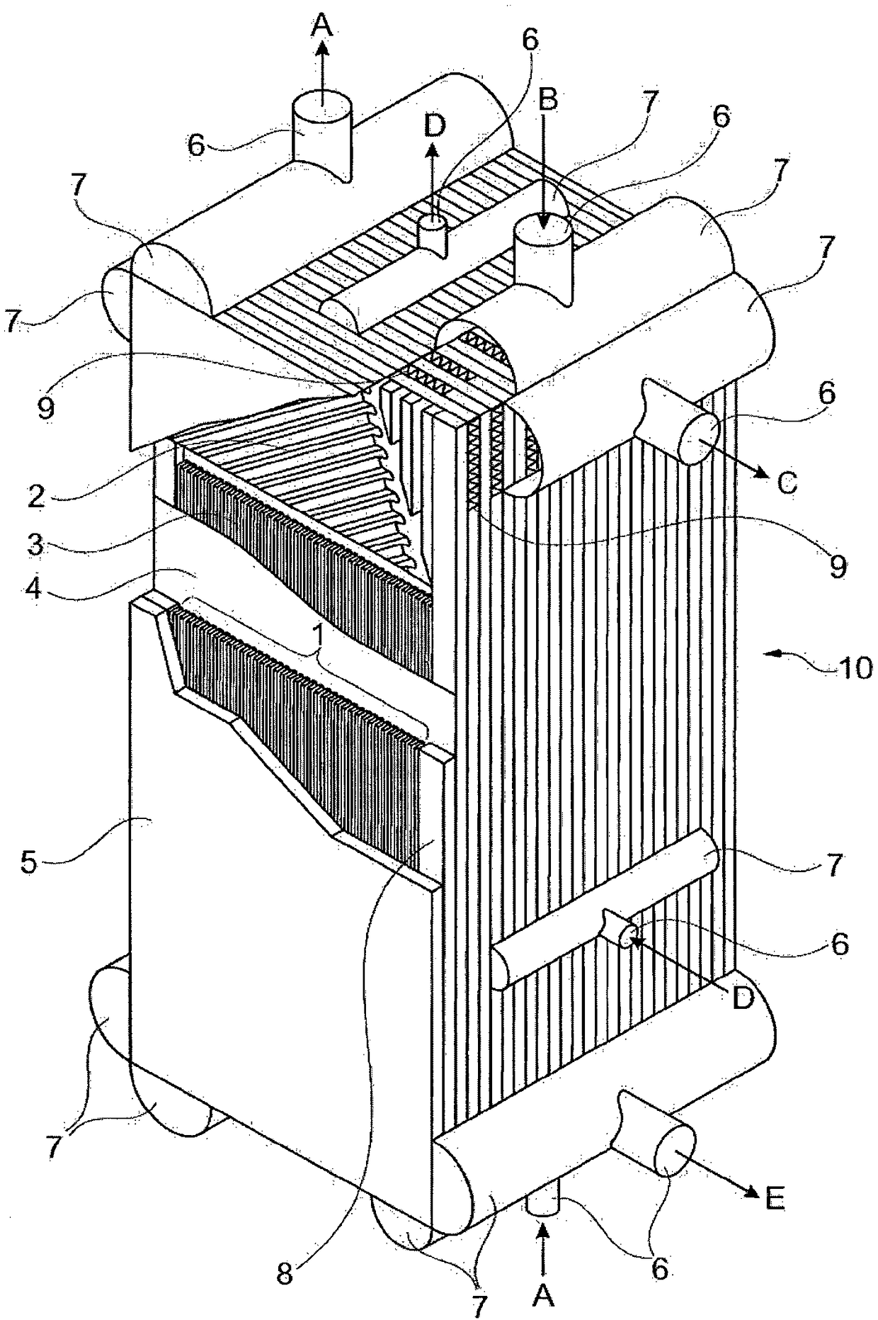
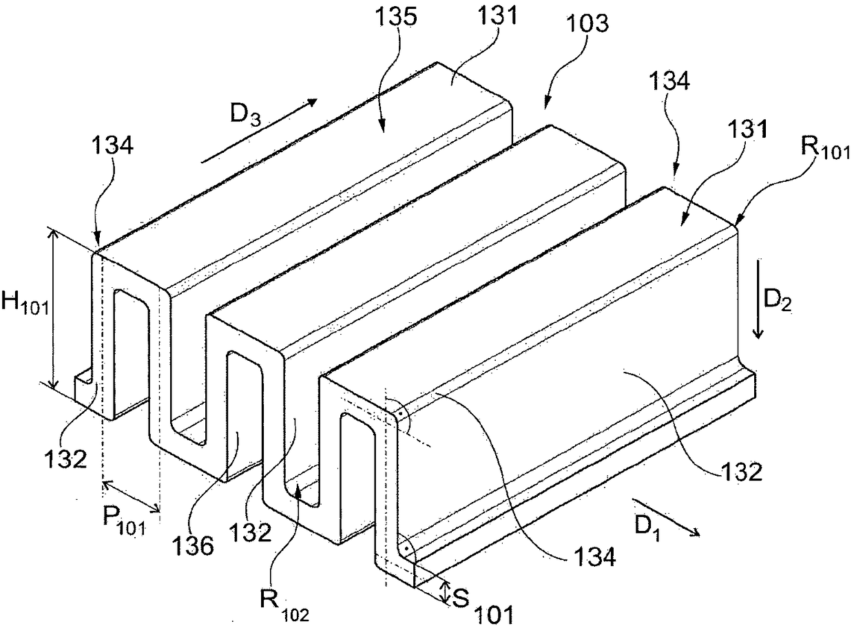
[0075] The plate heat exchanger according to FIG. 1 has already been described in the introduction of this description. A preferred embodiment of the plate heat exchanger according to the invention has the same structure as shown in Figure 1, but this is equipped with at least one image 3 , 5, 7, 8, 9 and 10 illustrate the fins 103 .

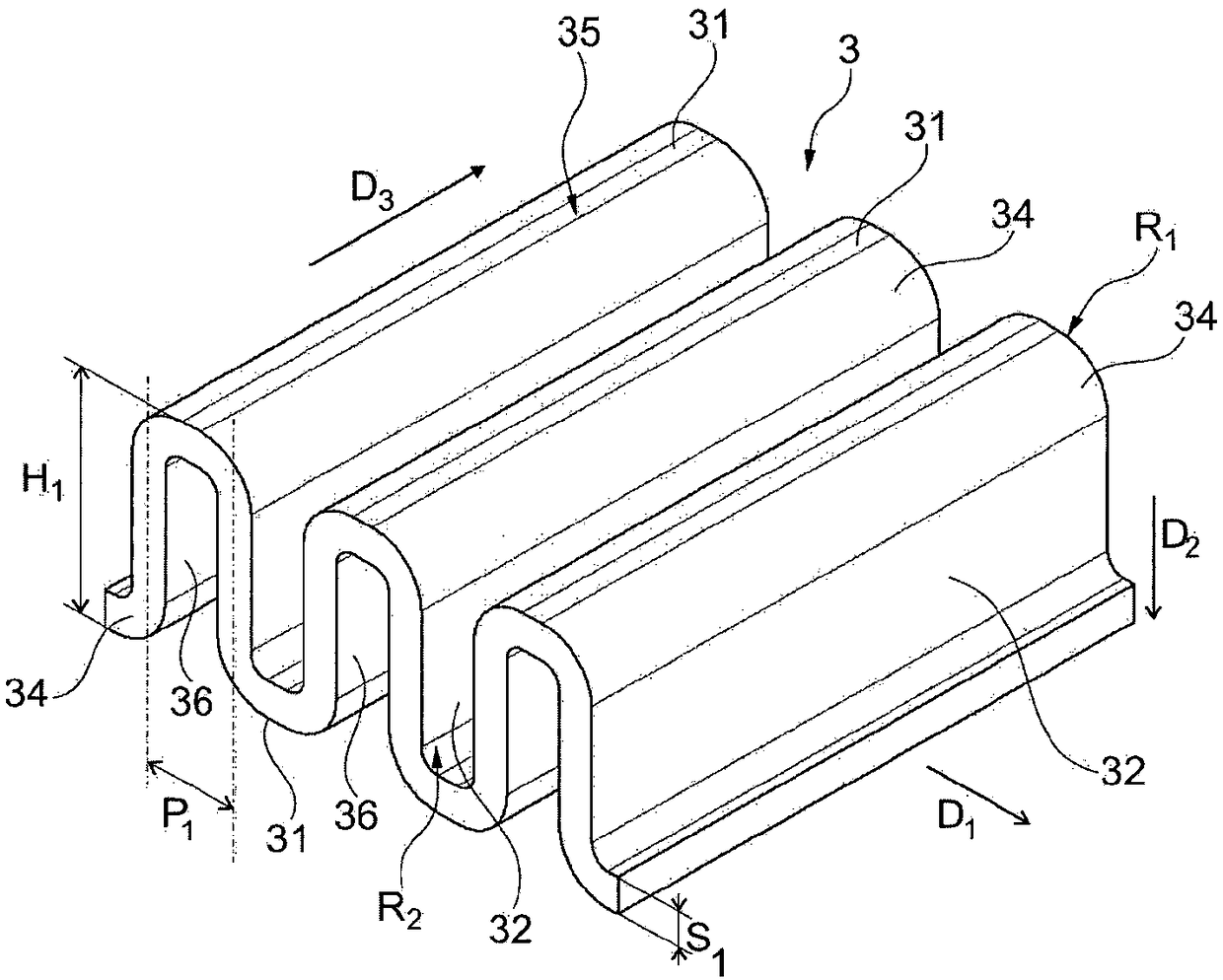
[0076] figure 2 A prior art fin 3 is shown, which is obtained by bending forming of a flat metal sheet having a wall thickness S1. The fins 3 have a corrugated structure with lower and upper wave crests 31 , which are connected to each other by wave webs 32 . The crest 31 and the corrugation web 32 are connected by a circular curved edge 34 , wherein the curved edge 34 each has an outer radius R1 and an inner radius R2 . The outer radius R1 of the curved edge 34 is determined by the inner radius R2 and the wall thickness S1. In the first spatial direction D1 , wave crests 31 and wave webs 32 alternately follow one another. The height H1 of...


PUM

PropertyMeasurementUnit
radiusaaaaaaaaaa
radiusaaaaaaaaaa
mean roughnessaaaaaaaaaa

Abstract

The present invention relates to a fin (103) for a plate heat exchanger having an angular, wave-shaped structure with wave crests (131) arranged in parallel to one another, wherein a wave crest (131)is connected via a wave flank (132) to another wave crest (131), and wherein the wave crest (131) and the wave flank (132) succeed one another in a first spatial direction (D1), and wherein the wave crest (131) and the wave flank (132) are connected to one another by a sheet edge (134). The wave crests (131) have a flat outer surface (135). According to the invention, the outer radius (R101) of the sheet edges (134) is 0.05 mm to 0.18 mm. A method for manufacturing a fin (103) is also provided, which comprises a pressure-shaping step in which a previously provided bent wave-shaped structure (3) is shaped such that the outer radius (R1) of the sheet edges (34) is reduced (R101).

Description

technical field [0001] The invention relates to a fin (Fin in English) for a brazed plate heat exchanger and a method for manufacturing such a fin. Furthermore, the invention relates to a brazed plate heat exchanger having such fins and to a method for producing a brazed plate heat exchanger. Background technique [0002] Fins are typically made from thin, flat sheets that are folded into a corrugated configuration by a press or other tool suitable for bending and forming. figure 2 An example of fins 3 formed by bending forming is shown. It has a plurality of wave crests 31 and wave webs 32 following one another in a first spatial direction ( D1 ). like Figure 11 As shown, after joining the heat exchanger block 10 in the brazing furnace, the wave crest 31 of the corrugated structure is connected surface-to-surface with the respective adjacent partition plate 4 by brazing. [0003] Fin 3 within path 1 fulfills three tasks: [0004] On the one hand, the heat exchange sur...

Claims


Application Information

Patent Timeline
Patent Type & Authority Applications(China)
IPC IPC(8): F28F3/02F28D9/00
CPCF28D9/00F28F3/02F28F9/18F28F21/084B23P15/26F28F3/027F28D9/0062F28F3/025F28F2275/04
Inventor M·G·罗纳赫
Owner LINDE AG
Learn More