Supercharge Your Innovation With Domain-Expert AI Agents!

linear power amplifier

A technology of power amplifier and power level, which is applied in the direction of power amplifier, amplifier, feedforward amplifier, etc., and can solve problems such as instability

Active Publication Date: 2021-08-31
QORVO US INC
View PDF8 Cites 0 Cited by
  • Summary
  • Abstract
  • Description
  • Claims
  • Application Information

AI Technical Summary

Problems solved by technology

Unfortunately, these feed-forward control systems have instability due to manufacturing variations, temperature variations, and power supply variations

Method used


Image

  • linear power amplifier
  • linear power amplifier
  • linear power amplifier

Examples


Embodiment Construction

[0014] The embodiments set forth below represent the necessary information to enable those skilled in the art to practice the disclosure, and illustrate the best mode of carrying out the disclosure. After reading the following description in light of the accompanying drawing figures, those skilled in the art will understand the concepts of the disclosure and will recognize applications of these concepts not particularly addressed herein. It should be understood that these concepts and applications are within the scope of this disclosure and the appended claims.

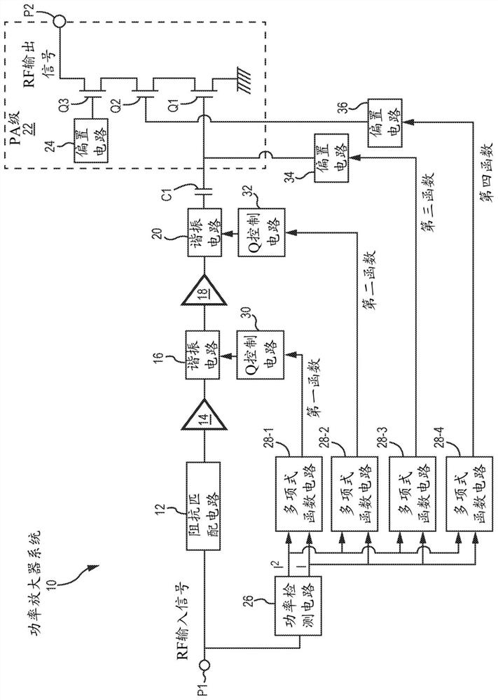
[0015] figure 1 is a block diagram of a power amplifier (PA) system 10 including transmit paths and control circuitry. The transmit path is coupled between the input port P1 and the output port P2. Input port P1 is configured to receive an input radio frequency (RF) signal, and output port P2 is configured to provide an RF output signal. The transmit path includes an impedance matching circuit 12 , a first preampli...


PUM


Abstract

The present invention relates to a power amplifier (PA) system provided in a semiconductor device and having feedforward gain control. The PA system includes a transmission path and a control circuit. The transmit path is configured to amplify an input radio frequency (RF) signal and includes a first resonant circuit and a PA stage. The control circuit is configured to detect a power level associated with the input RF signal and to control a first bias signal provided to the PA stage based on a first function of the power level and based on the A second function of the power level to control the quality factor (Q) of the first resonant circuit.

Description

[0001] related application [0002] This application claims the benefit of US Provisional Patent Application No. 62 / 168,366, filed May 29, 2015, the disclosure of which is incorporated herein by reference in its entirety. technical field [0003] The present disclosure relates to power amplifier output power level control and linearization based on input power level detection. Background technique [0004] Many modern electronic devices include wireless communication circuitry for processing and transmitting radio frequency (RF) signals. For example, an electronic device may include wireless local area network (WLAN) circuitry, cellular communication circuitry, or the like. A power amplifier (PA) is used to provide amplification of the RF signal. To reduce distortion, the PA may include a closed-loop control system to stabilize the performance of the PA. Unfortunately, closed-loop control systems are usually limited in power range when they are active. For example, when ...

Claims


Application Information

Patent Timeline
Patent Type & Authority Patents(China)
IPC IPC(8): H03F1/32H03F3/195H03G1/00H03G3/30H03F1/22H03F1/02H03F1/56H03F3/24
CPCH03F1/0266H03F1/223H03F1/3205H03F1/3223H03F1/3258H03F1/56H03F3/195H03F3/245H03F2200/108H03F2200/18H03F2200/211H03F2200/222H03F2200/228H03F2200/234H03F2200/246H03F2200/301H03F2200/318H03F2200/321H03F2200/408H03F2200/42H03F2200/435H03F2200/451H03F2200/465H03F2200/61H03F2200/75H03F2200/99H03F2201/3212H03F2201/3218H03G3/3042H03G2201/106H03G2201/40H03F1/0205H03F3/193H03F3/21
Inventor 史蒂文·詹姆斯·弗兰克王鑫阿里礼萨·欧斯寇伊
Owner QORVO US INC
Features
  • R&D
  • Intellectual Property
  • Life Sciences
  • Materials
  • Tech Scout
  • Unparalleled Data Quality
  • Higher Quality Content
  • 60% Fewer Hallucinations
Learn More