Ultrasonic TOFD (Time of Flight Diffraction) detection method for weld defects based on linear frequency modulation technology

A technology of linear frequency modulation and detection method, which is applied in the analysis of solids using sonic/ultrasonic/infrasonic waves, which can solve the problem of conflict between signal propagation distance and resolution.

Inactive Publication Date: 2013-08-07
HARBIN INST OF TECH
View PDF2 Cites 21 Cited by
  • Summary
  • Abstract
  • Description
  • Claims
  • Application Information

AI Technical Summary

Problems solved by technology

[0015] The purpose of the present invention is to provide an ultrasonic TOFD detection method for weld defects based on linear frequency modulation technology

Method used


Image

  • Ultrasonic TOFD (Time of Flight Diffraction) detection method for weld defects based on linear frequency modulation technology
  • Ultrasonic TOFD (Time of Flight Diffraction) detection method for weld defects based on linear frequency modulation technology
  • Ultrasonic TOFD (Time of Flight Diffraction) detection method for weld defects based on linear frequency modulation technology

Examples


specific Embodiment approach 1

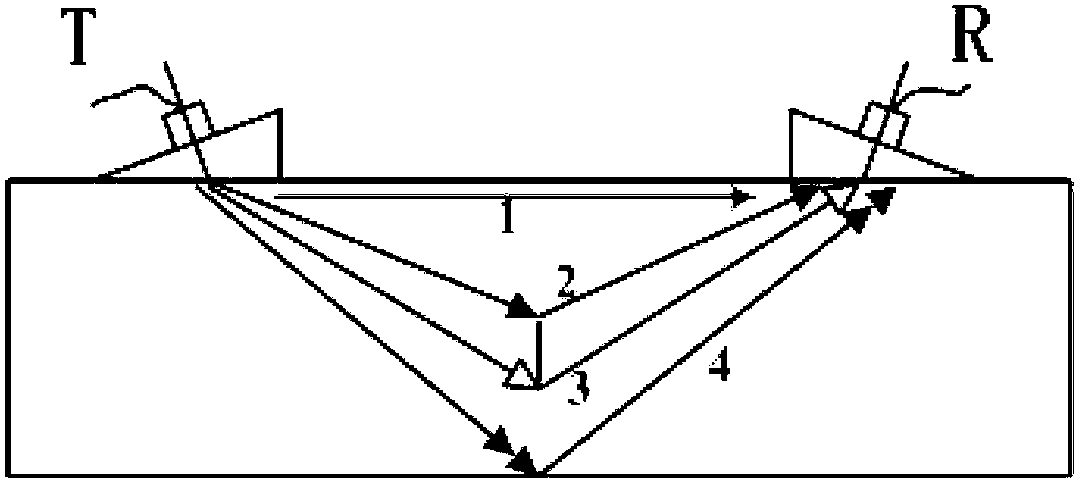
[0054] Specific implementation mode one: combine Figure 4 Describe this embodiment, the method of this embodiment includes the following steps: step 1, the ultrasonic transmitting probe and the receiving probe are symmetrically distributed on both sides of the detected position, the preferred digital signal generator generates a broadband LFM pulse signal, and simultaneously generates a synchronous trigger signal for excitation Broadband signal receiver, the wideband LFM pulse signal is amplified by a linear power amplifier to have the corresponding energy to excite the ultrasonic transmitting probe;

[0055] The LFM pulse signal is generated by a digital method, and the mathematical expression of the linear frequency modulation signal is

[0056] s(t)=Arect(t / T)cos(2πf c t±Kπt 2 ) |t|≤T / 2 (3)

[0057] where A is the signal amplitude, f c is the carrier frequency, K=B / T is the change slope of the instantaneous frequency of the signal, that is, the frequency modulation slo...

specific Embodiment approach 2

[0089] Specific implementation mode two: combination figure 1 Describe this embodiment, the broadband signal receiver of this embodiment is UT-350 broadband signal receiver, can receive the signal of relatively wide frequency band, its highest sampling frequency is 50MHz. Other implementation steps are the same as those in the first embodiment.

specific Embodiment approach 3

[0090] Specific implementation mode three: combination figure 1 This embodiment will be described. The linear power amplifier in this embodiment is a linear power amplifier A150, which can linearly amplify an input signal with a gain of 53 dB. Other implementation steps are the same as those in the first embodiment.


PUM

PropertyMeasurementUnit
Depthaaaaaaaaaa

Abstract

The invention discloses an ultrasonic TOFD (Time of Flight Diffraction) detection method for weld defects based on a linear frequency modulation technology, relating to an ultrasonic detection method for weld defects. The method solves the problem that in the existing ultrasonic detection for large-thickness welding structures, the signal propagation distance and the resolution ratio are mutually contradicted. The method comprises the following steps that: a digital signal generator produces a wideband (Linear Frequency Modulation) LFM pulse signal, and the wideband LFM pulse signal is amplified through a linear power amplifier so as to have corresponding energy for exciting an ultrasound transmitting probe; the ultrasound transmitting probe after being excited produces forced vibration and radiates ultrasonic waves to a test piece; when a control computer executes an acquisition command, a receiving probe receives a detection signal at a corresponding position, and the receiving of the detection signal is completed by a wideband signal acquisition card; and the computer carries out matched filtering processing on the received signal, so that a pulse compression signal is obtained, and according to the time that each wave reaches, the buried depth of a defect can be calculated according to a formula. The method disclosed by the invention is used for detecting weld defects.

Description

technical field [0001] The invention relates to an ultrasonic detection method for welding seam defects. Background technique [0002] Large-thickness welded structures are widely used in boilers, pressure vessels, shipbuilding and other fields. Because these structures are often in extreme environments such as high temperature, high pressure or high load, the requirements for welding quality are high to prevent accidents. As one of the quality control methods, ultrasonic testing technology plays an important role in the detection of large-thickness welded structures, especially in recent years, the newly developed detection technology based on Time of Flight Diffraction (TOFD) has replaced the X-ray inspection. However, with the increasingly stringent requirements for quality and reliability of large-scale welded structures, the requirements for ultrasonic testing technology are also getting higher and higher, that is, it is necessary to accurately determine whether there ...

Claims


Application Information

Patent Timeline
IPC IPC(8): G01N29/07
Inventor 刚铁盛朝阳丛森
Owner HARBIN INST OF TECH
Why Eureka
Try Eureka