Unlock instant, AI-driven research and patent intelligence for your innovation.

Video delivery device, video delivery system, and video delivery method

A technology for video and video signals, applied in video distribution devices, video distribution systems and video distribution fields, can solve problems such as inability to transmit 3D video signals, and achieve the effect of improving transmission efficiency and transmission speed

Active Publication Date: 2018-06-08
MITSUBISHI ELECTRIC CORP
View PDF4 Cites 0 Cited by
  • Summary
  • Abstract
  • Description
  • Claims
  • Application Information

AI Technical Summary

Problems solved by technology

On the contrary, in the transmission system described in the above-mentioned Patent Document 1, there is a problem that a 3D video signal cannot be transmitted when a plurality of 2D video signals are transmitted.

Method used


Image

  • Video delivery device, video delivery system, and video delivery method
  • Video delivery device, video delivery system, and video delivery method
  • Video delivery device, video delivery system, and video delivery method

Examples


Embodiment approach 1

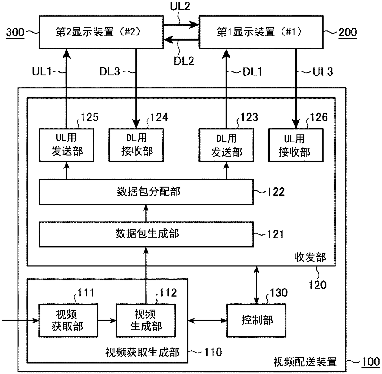
[0030] figure 1 It is a block diagram showing a configuration example of the video distribution system according to Embodiment 1 of the present invention. The video distribution system includes a video distribution device 100 and one or more display devices wired to the video distribution device 100 via a ring network.

[0031] exist figure 1 In the example shown above, two display devices, the first display device 200 and the second display device 300 , are connected to the video distribution device 100 , but one or three or more display devices may be connected. In this ring network, the transmission line through which video signals are transmitted from the video distribution device 100 in the order of the first display device 200 and the second display device 300 is called a downlink (hereinafter referred to as DL). The transmission line through which video signals are transmitted in the order of the second display device 300 and the first display device 200 is called an ...

Embodiment approach 2

[0073] In the first embodiment described above, the downlink and uplink packets distributed via the transmission line are not used for video display in the video distribution device 100 . Therefore, the packets received by the DL receiving unit 124 and the UL receiving unit 126 of the video distribution device 100 are discarded. On the other hand, in Embodiment 2, this data packet is used in the fault diagnosis of the video distribution system in order to improve the transmission quality.

[0074] Image 6 It is a block diagram showing a configuration example of a video distribution system according to Embodiment 2 of the present invention. The video distribution system includes a video distribution device 100a, and a first display device 200 and a second display device 300 wired to the video distribution device 100a via a ring network. exist Image 6 In, about with figure 1 as well as Figure 4 The same or equivalent parts are assigned the same reference numerals and des...


PUM


Abstract

A video delivery device provided with one or more display devices connected by a ring network, and a transmission / reception unit for transmitting / receiving a 2D or 3D video signal. This transmission / reception unit has a transmission unit for UL and a reception unit for UL for transmitting / receiving a video signal in an uplink of the ring network, and a transmission unit for DL and a reception unitfor DL for transmitting / receiving a video signal in a downlink of the ring network. When transmitting / receiving a 2D video signal, the transmission unit for DL and the reception unit for DL transmit / receive the 2D video signal. When transmitting / receiving a 3D video signal, the transmission unit for DL and the reception unit for DL transmit / receive a video signal for the left eye and the transmission unit for UL and the reception unit for UL transmit / receive a video signal for the right eye.

Description

technical field [0001] The present invention relates to a video distribution device for distributing two-dimensional (2D) video and three-dimensional (3D) video to a display device, a video distribution system including a display device and a video distribution device, and a video distribution system for distributing 2D video and 3D video to a display device Distribution Method. Background technique [0002] In recent years, with the advancement of video processing technology, the high precision of video has been continuously promoted. The resolution of full high-definition TV, which is the mainstream of home TV, is 2K (1920×1080 pixels), and 4K TV with 4 times the resolution has begun to be put into practical use, and 8K TV with 16 times the resolution is also close to being put into practical use. In addition, not only conventional 2D video, but also 3D video that is stereoscopic video has been popularized. In principle, in order to display a 3D video, separate videos ar...

Claims


Application Information

Patent Timeline
IPC IPC(8): H04N21/462H04N13/194H04N13/359H04N21/61H04N13/30
CPCH04N13/161H04N21/6156H04N21/816H04N13/194H04N13/30H04N21/462H04N21/236H04N21/6106H04N21/6473
Inventor 星原靖宪加藤圣崇
Owner MITSUBISHI ELECTRIC CORP