Grinding method for pipe end portions in batches

A batch grinding and pipe technology, which is applied to machine tools, grinders, grinding workpiece supports and other directions suitable for grinding workpiece edges, which can solve the problems of easily pinching hands and affecting processing efficiency.

Active Publication Date: 2018-06-12
TIANJIN SAIXIANG M&E ENG CO LTD
View PDF5 Cites 2 Cited by
  • Summary
  • Abstract
  • Description
  • Claims
  • Application Information

AI Technical Summary

Problems solved by technology

In the process of clamping the shaft tube, people often need to place the shaft tube on the clamping position, and manually toggle the clamping switch to make the clamping mech

Method used


Image

  • Grinding method for pipe end portions in batches
  • Grinding method for pipe end portions in batches
  • Grinding method for pipe end portions in batches

Examples


Embodiment Construction

[0029] The following is further described in detail through specific implementation methods:

[0030] The reference signs in the accompanying drawings of the specification include:

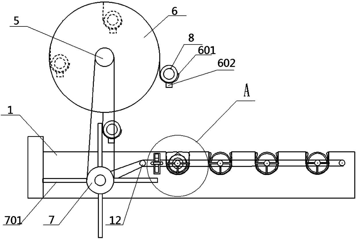
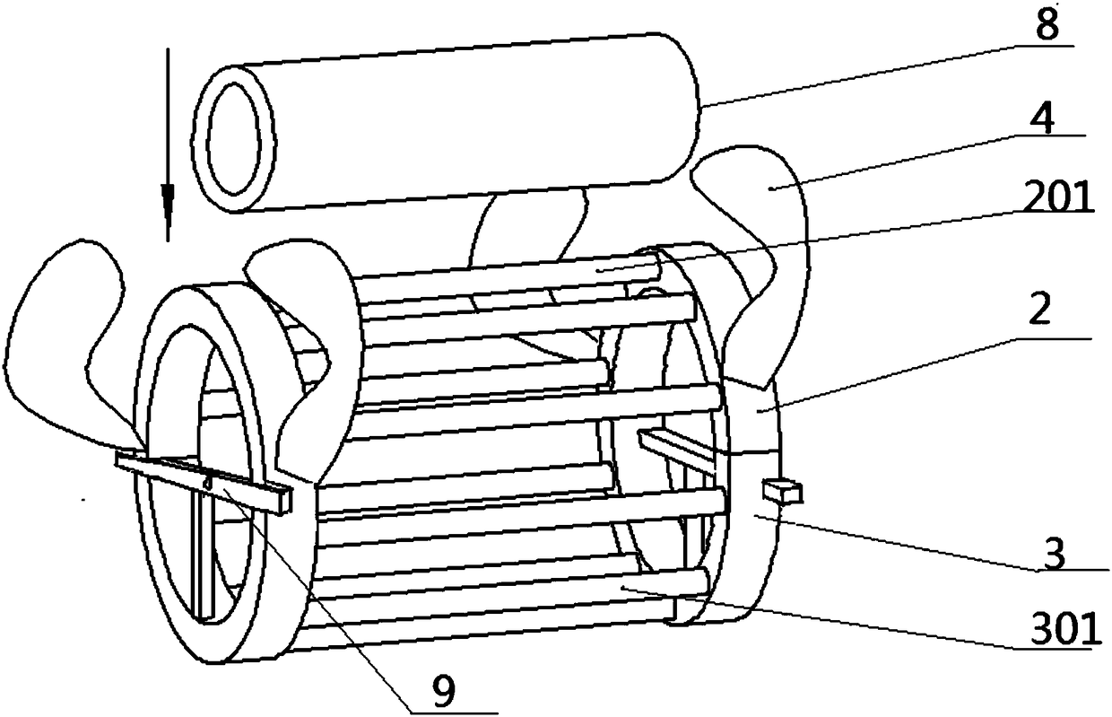
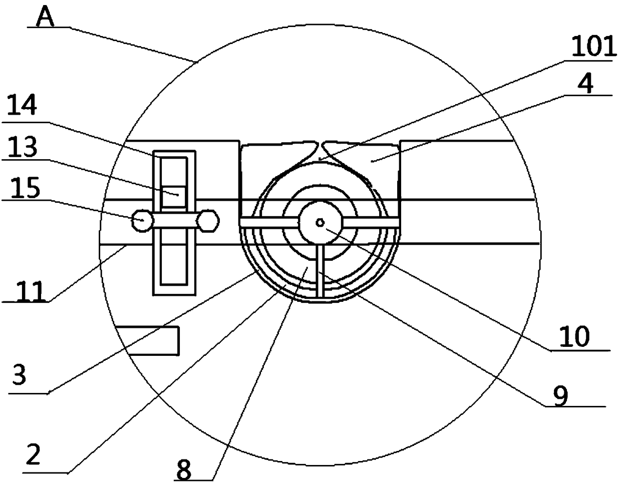
[0031] Processing table 1, groove 101, upper half ring 2, upper branch pipe 201, lower half ring 3, lower branch pipe 301, air bag 4, rotating shaft 5, first transmission plate 6, hook 601, counterweight 602, runner 7, Driving rod 701, shaft tube 8, support 9, sprocket wheel 10, chain 11, guide wheel 12, friction block 13, rectangular frame 14, friction wheel 15.

[0032] A batch grinding method for pipe ends comprising the following steps:

[0033] Step 1: Prepare materials: four pipes to be polished, grinding equipment, and the structure of the grinding equipment is as follows figure 1 , figure 2 with image 3 Shown:

[0034] Including frame, processing table 1, transmission mechanism and grinding mechanism, wherein:

[0035] The right part of the processing table 1 is provided with a plu...


PUM


Abstract

The invention relates to the field of grinding and machining, in particular to a grinding method for pipe end portions in batches. The grinding method includes the steps that step 1, shaft pipes and grinding equipment are prepared, and the grinding equipment includes a transport disc and a grinding part; step 2, the shaft pipes are placed on the transport disc; step 3, the shaft pipes are transported through the transport disc; step 4, the shaft pipes on the transport disc are unloaded on the grinding equipment; step 5, the shaft pipes are fixed; step 6, the grinding equipment is started, andthe grinding speed is regulated; and step 7, the shaft pipes after grinding are taken out, and the grinding for next batch of shaft pipes is prepared. According to the grinding method for the pipe endportions in batches, the automatic clamping and the synchronous grinding of the multiple shaft pipes can be achieved, and the machining efficiency of the shaft pipes is improved.

Description

technical field [0001] The invention relates to the field of mechanical processing, in particular to a batch grinding method for pipe ends. Background technique [0002] Existing pipes, such as shaft pipes, have sharp inner and outer edges after cutting, and also produce burrs, which will cause damage to workers or packaging during operation or transportation, which is very dangerous. Therefore, the end of the shaft tube needs to be polished after cutting. The existing grinding device for the shaft tube includes a clamping mechanism. After the shaft tube is clamped by the clamping mechanism, the end of the shaft tube is polished. In the process of clamping the shaft tube, people often need to place the shaft tube on the clamping position, and manually toggle the clamping switch to make the clamping mechanism work to clamp the shaft tube. When grinding in batches, the shaft tubes are manually reciprocated, which affects the processing efficiency and is easy to pinch the hand...

Claims


Application Information

Patent Timeline
IPC IPC(8): B24B1/00B24B9/00B24B41/06
CPCB24B1/00B24B9/007B24B41/06
Inventor 熊顺斌
Owner TIANJIN SAIXIANG M&E ENG CO LTD
Why Eureka
Try Eureka