Thick Oil Mixed Thin Mixing Tool

A technology for heavy oil and tools, applied in the field of oil production equipment, can solve the problems of increased energy consumption of the oil pumping system, high mixing pressure, waste of thin oil, etc., to enhance the jet effect of thin oil, reduce the oil hydraulic pressure, and reduce the failure rate. Effect

Active Publication Date: 2020-02-14
CHINA PETROLEUM & CHEM CORP
View PDF13 Cites 0 Cited by
  • Summary
  • Abstract
  • Description
  • Claims
  • Application Information

AI Technical Summary

Problems solved by technology

[0004] At present, the common problem of the mixer is that the mixing effect is not ideal, and the phenomenon of slug flow often occurs during the oil lifting process; in addition, the pressure drop of the mixing is large, which causes the energy consumption of the oil pumping system to increase, and the increase of the amount of dilution will cause A large amount of thin oil wasted

Method used


Image

  • Thick Oil Mixed Thin Mixing Tool
  • Thick Oil Mixed Thin Mixing Tool
  • Thick Oil Mixed Thin Mixing Tool

Examples


Embodiment Construction

[0036] The embodiments of the technical solution of the present invention will be described in detail below in conjunction with the accompanying drawings. The following embodiments are only used to explain the technical solutions of the present invention more clearly, and therefore are only used as examples, and cannot be used to limit the protection scope of the present invention.

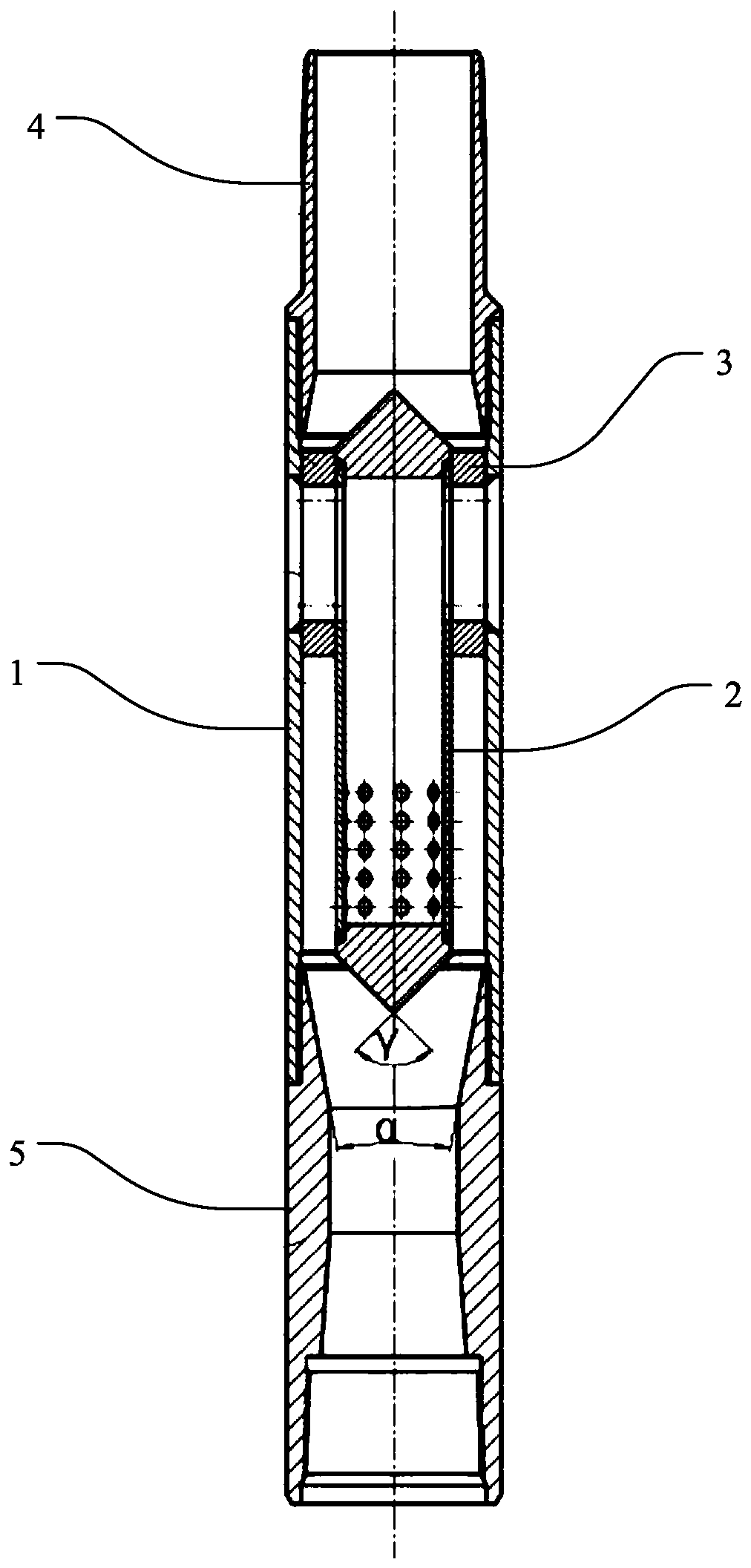
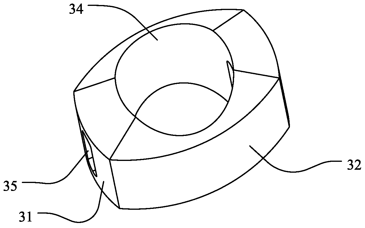
[0037] Such as Figure 1 to Figure 8 As shown, the present invention provides a thick oil blending and mixing tool, which includes an outer cylinder 1, a spray tube 2, a support block, a first joint 4 and a second joint 5, the first joint 4 and the second joint 5 respectively Connected to both ends of the outer cylinder 1, and the spray tube 2 is sleeved in the outer cylinder 1. In this embodiment, the first joint 4 and the second joint 5 are respectively connected to the outer cylinder 1 through a threaded connection, and the spray tube 2 and the outer cylinder 1 are arranged coaxially. The two en...


PUM


Abstract

The invention discloses a thickened oil blending-light mixed tool. The thickened oil blending-light mixed tool includes an outer tube, an injection pipe, a support block, a first joint and a second joint; the first joint and the second joint are separately connected to two ends of the outer tube, the outer tube is sleeved with the injection pipe, and two ends of the injection pipe is closed; the perimeter wall, close to the first joint, of the injection pipe is provided with a thin oil inlet which is used for passing of thin oil into the injection pipe, the perimeter wall, close to one end ofthe second joint, of the injection pipe is provided with a jet hole which is an annular gap formed between an outer tube and an inner tube, and the gap allows the thickened oil to enter from the firstjoint and to flow in the direction of the second joint; the thin oil enters the injection tube from the thin oil inlet and flows in the direction of the jet hole to be ejected from the jet hole, a first-time mixing of the thin oil and the flowed thickened oil is carried out, and mixed oil enters the second joint for a second-time mixing. According to the thickened oil blending-light mixed tool, the thin oil and the thickened oil can be fully mixed, the thin oil consumption is reduced, so that the effect of reducing the energy consumption can be achieved.

Description

Technical field [0001] The invention relates to the technical field of oil production equipment, in particular to a heavy oil blending and dilute mixing tool. Background technique [0002] Dilution and viscosity reduction is an important technology for heavy oil production, and the mixer is the main tool to improve the mixing effect in this process. Crude oil has good fluidity under formation conditions, but after entering the wellbore, as the temperature of the wellbore decreases during the vertical upward flow process, the viscosity of the crude oil increases and the fluidity deteriorates, making the oil well unable to put into production and maintain production. Mixing thin oil to reduce viscosity is one of the main forms in the heavy oil production process. Thin oil is injected from the annulus of the oil jacket, and after reaching the thinning point, it is mixed with the heavy oil and enters the tubing to achieve the purpose of viscosity reduction and lifting of the heavy oi...

Claims


Application Information

Patent Timeline
Patent Type & Authority Patents(China)
IPC IPC(8): E21B43/16
CPCE21B43/16
Inventor 张园彭振华丁雯许强任向海高定祥康红兵王轲张翼
Owner CHINA PETROLEUM & CHEM CORP
Why Eureka
Try Eureka