Supercharge Your Innovation With Domain-Expert AI Agents!

Switch control circuit for household appliances

A technology for switch control and household appliances, applied in control/regulating systems, instruments, regulating electrical variables, etc., can solve the problems of easy aging of mechanical contact points, poor circuit reliability, and unusable machines, and achieve the effect of avoiding unusable machines.

Inactive Publication Date: 2018-06-12
ANHUI TAIDE ELECTRONICS TECH
View PDF5 Cites 0 Cited by
  • Summary
  • Abstract
  • Description
  • Claims
  • Application Information

AI Technical Summary

Problems solved by technology

[0002] At present, with the popularization of intelligent household appliances, the structural practicability of the switch device circuit of household appliances is a key point in this technical field; Poor performance, mechanical contact points are prone to aging, making the machine unusable

Method used


Image

  • Switch control circuit for household appliances

Examples


Embodiment Construction

[0016] The present invention will be further explained below in conjunction with the accompanying drawings and specific embodiments. It should be understood that the following specific embodiments are only used to illustrate the present invention and are not intended to limit the scope of the present invention.

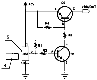
[0017] As shown in the figure, a household appliance switch control circuit includes a magnetic induction Hall element U1, a triode Q1, a triode Q2, a resistor R1, a resistor R2, a resistor R3, a resistor R4, and a power supply; the pin 1 of the magnetic induction Hall element U1 is connected to the power supply Connection, 2 pins are connected to one end of the resistor R1 and one end of the resistor R2 respectively, 3 pins are grounded; the C pole of the triode Q1 is connected to one end of the resistor R3, the B pole is connected to the other end of the resistor R2, and the E pole is grounded; the triode Q2 The pole C is connected to the output terminal of the power...


PUM


Abstract

The invention provides a switch control circuit for household appliances. The switch control circuit for household appliances comprises a magnetic induction Hall element U1, an audion Q1, an audion Q2, a resistor R1, a resistor R2, a resistor R3, a resistor R4 and a power supply; the pin 1 of the magnetic induction Hall element U1 is connected with the power supply, the pin 2 is respectively connected with one end of the resistor R1and one end of the resistor R2, and the pin 3 is grounded; the pole C of the audion Q1 is connected with one end of the resistor R3, the pole B is connected with the other end of the resistor R2, and the pole E is grounded; the pole C of the audion Q2 is connected with one end of the output end VDD / OUT of the power supply, the pole B is respectively connectedwith the other end of the resistor R3 and one end of the resistor R4, and the pole E is connected with the power supply; the other end of the resistor R1 and the other end of the resistor R4 are bothconnected with the power supply. Compared with the prior art, the switch control circuit for the household appliances has the advantages that conventional component combination is adopted, the switchmode has no mechanical contact point, and the situation that the machine can not be used due to contact point aging can be effectively avoided.

Description

technical field [0001] The invention relates to the technical field of switch control circuits, in particular to a switch control circuit for household appliances. Background technique [0002] At present, with the popularization of intelligent household appliances, the structural practicability of the switch device circuit of household appliances is a key point in this technical field; The performance is poor, and the mechanical contact point is easy to age, which makes the machine unusable. The control circuit adopts the combination of conventional components, and the switch mode has no mechanical contact point, which can avoid the machine from being unusable due to the aging of the contact point. Contents of the invention [0003] In order to solve the above problems, the present invention discloses a switch control circuit for household appliances. [0004] In order to achieve the above object, the present invention provides the following technical solutions: [000...

Claims


Application Information

Patent Timeline
Patent Type & Authority Applications(China)
IPC IPC(8): G05F1/625
CPCG05F1/625
Inventor 陈明生张万霞祝开峰欧阳修汪锦荣徐斌张萍陆有明万琴
Owner ANHUI TAIDE ELECTRONICS TECH
Features
  • R&D
  • Intellectual Property
  • Life Sciences
  • Materials
  • Tech Scout
  • Unparalleled Data Quality
  • Higher Quality Content
  • 60% Fewer Hallucinations
Learn More