An operating microscope pedestal for clinical general surgery

An operating microscope and general surgery technology, which is applied in the field of medical devices, can solve the problems such as cumbersome replacement of the counterweight of the device, and achieve the effects of simple and reliable base structure and reduced manufacturing cost.

Inactive Publication Date: 2018-06-15
李文文
View PDF1 Cites 2 Cited by
  • Summary
  • Abstract
  • Description
  • Claims
  • Application Information

AI Technical Summary

Problems solved by technology

[0005] The technical problem to be solved by the present invention is: in order to solve the problems existing in the above-mentioned background technology, provide a kind of operating microscope base for clinical general surgery, solve the problem of cumbersome replacement operation of the counterweight of the existing device

Method used


Image

  • An operating microscope pedestal for clinical general surgery
  • An operating microscope pedestal for clinical general surgery

Examples


Embodiment 1

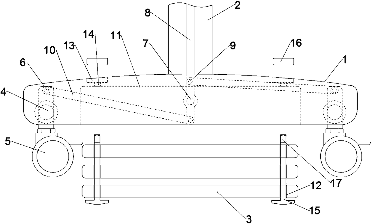
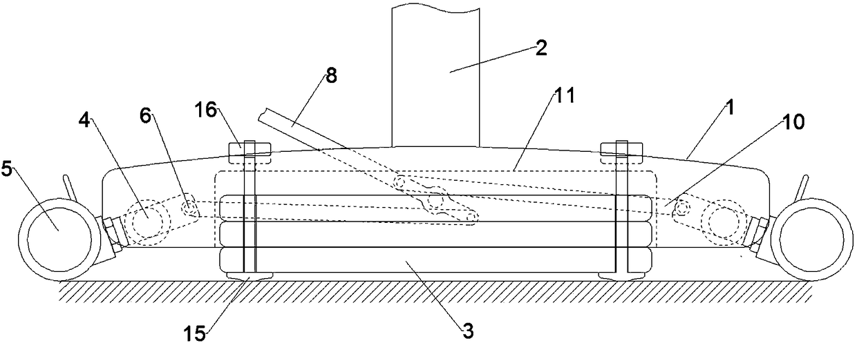
[0015] Embodiment 1: When carrying out counterweight for the microscope base, a clinical general surgery operating microscope base includes a base body 1, a bracket 2 and a counterweight 3 fixedly connected to the middle part of the upper surface of the base body 1, four inside of the base body 1 The two angles are respectively movably connected to the second rotating shaft 4, and one end of the second rotating shaft 4 is fixedly connected to the universal wheel 5, and the other end of the second rotating shaft 4 is fixedly provided with a rotating hole 6, and the universal wheel 5 can rotate relative to the base body 1, The inside of the base body 1 is located directly below the bracket 2 and is movably connected to the first rotating shaft 7. The tie rod 8 is fixedly connected to the first rotating shaft 7. The tie rod 8 is located at the joint of the first rotating shaft 7. A pair of pull holes 9 are symmetrically opened, and the two ends of the cross bar 10 are respectively ...

Embodiment 2

[0018] Embodiment 2: When not in use, a clinical general surgery operating microscope base includes a base body 1, which is fixedly connected to the bracket 2 and the counterweight 3 in the middle of the upper surface of the base body 1, and the four corners inside the base body 1 are movable respectively Connected to the second rotating shaft 4, one end of the second rotating shaft 4 is fixedly connected to the universal wheel 5, the other end of the second rotating shaft 4 is fixed with a rotating hole 6, the universal wheel 5 can rotate relative to the base body 1, and the inside of the base body 1 The first rotating shaft 7 is movably connected directly below the bracket 2, and the tie rod 8 is fixedly connected to the first rotating shaft 7. The tie rod 8 is located at the joint of the first rotating shaft 7 and a pair of drawing holes 9 are symmetrically opened, and the two ends of the cross bar 10 are respectively fixedly connected to the rotating holes 6 And drawing hol...


PUM


Abstract

The invention relates to the technical field of medical instruments and particular provides an operating microscope pedestal for clinical general surgery. Universal wheels can rotate and move relativeto a pedestal body; a first rotating shaft is movably connected to the inside of the pedestal body right under a support; a pull rod is fixedly connected to the first rotating shaft; the pull rod issymmetrically provided with a pair of pull holes at the joint of the first rotating shaft; two ends of cross rods are fixedly connected to rotating holes and the pull holes; the bottom surface of thepedestal body is fixedly provided with a counter weight groove and the four corners of a counter weight block are fixedly provided with fixing holes. Each universal wheel comprises an installing base,a fixing rack and a wheel, wherein the wheel is connected to the fixing rack via a screw and the screw is provided with a clamping member; the universal wheels are fixed to the bottom of the apparatus via the installing bases and each fixing rack can be rotatably fixed to the bottom of the corresponding installing base via a central rivet in the vertical direction. The support comprises an uppersupporting plate and a lower supporting plate which are arranged in parallel in a spaced manner; the upper supporting plate and the lower supporting plate are connected via a stand pillar; the surfacearea of the upper supporting plate is less than that of the lower supporting plate.

Description

technical field [0001] The invention relates to the technical field of medical instruments, in particular to an operating microscope base for clinical general surgery. Background technique [0002] In surgical microscopes, such as ophthalmic surgical microscopes, surgical microscope stands are used to support microscope heads of different configurations and weights. Surgical microscopes with a floor stand rest on the ground with the aid of a base at the bottom end of the stand. Casters are arranged on the base to facilitate the movement of the entire operating microscope stand and change its relative position on the ground. In order to balance the different weights of microscope heads with different configurations, it is required that the weight of the base can be changed as needed. In the existing operating microscope stand, the required base weight is adjusted by adding or subtracting additional counterweights. When the microscope head is relatively heavy, adding a coun...

Claims


Application Information

Patent Timeline
Patent Type & Authority Applications(China)
IPC IPC(8): A61B90/25A61B90/20A61B90/50
CPCA61B90/25A61B90/20A61B90/50A61B2090/5025A61B2090/504
Inventor 李文文
Owner 李文文
Why Eureka
Try Eureka