Head massage device

A head and control device technology, applied in the direction of roller massage, massage auxiliary products, physical therapy, etc., can solve the problems of different massage methods, single massage method, poor experience, etc., so as to avoid numbness, Less material, soft massage effect

Inactive Publication Date: 2018-06-15
袁超
View PDF6 Cites 3 Cited by
  • Summary
  • Abstract
  • Description
  • Claims
  • Application Information

AI Technical Summary

Problems solved by technology

[0003] At present, most of the head massage devices on the market are head-mounted and have a single massage method. The massage principle is mostly based on the vibration principle, and it is impossible to perform different massages on different parts. It has not yet appeared on the market, and different massage devices can achieve better massage effects according to different parts; in addition, most of the head massagers on the market currently use vibration to achieve massage, and long-term use will cause local numbness. poor
There are also some head massagers that use a large number of electronic devices, and the cost is relatively high.

Method used


Image

  • Head massage device
  • Head massage device
  • Head massage device

Examples


Embodiment 1

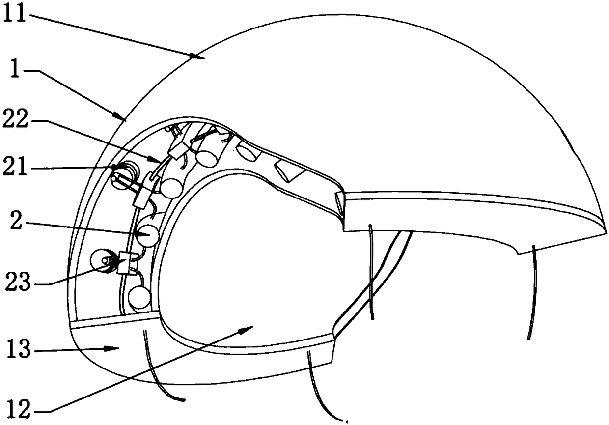
[0028] Such as figure 1 , figure 2 As shown, a head massaging device of this embodiment includes a housing 1 and a pushing body 2; the housing 1 includes an outer shell 11, an inner core 12, a connecting plate 13 and a tether 14; the outer shell 11 is a hemispherical shell, and the front and rear ends of the shell 11 have the same arc-shaped gap, and the shell 11 has a certain rigidity and elasticity; The inner core 12 is a flexible material; the connecting plate 13 is two thin plates connecting the outer shell 11 and the inner core 12; Rope 14 is non-elastic material.

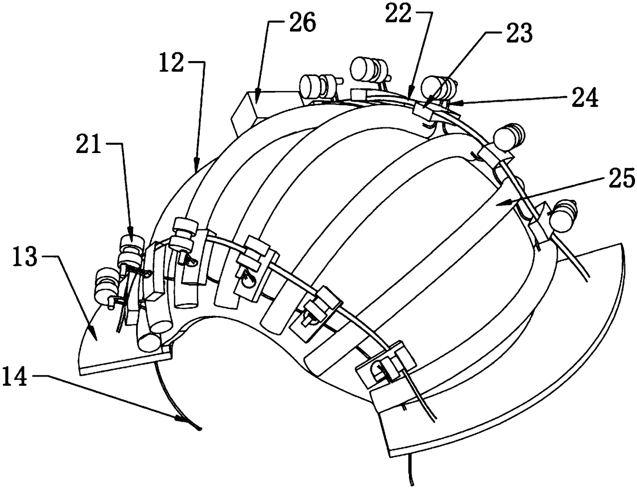
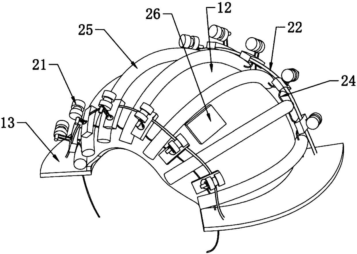
[0029] Such as image 3 , Figure 6 As shown, the pushing body 2 includes a massage device 21, a support bar 22, a limit block 23, a pull cord 24, a push rod 25 and a control device 26; the massage device 21 is six pairs of evenly consolidated When the output shafts at the two gaps inside the casing 11 are at the eccentric position of the massage device rotation center, and one of the output shafts of th...

Embodiment 2

[0032] Such as figure 1 , figure 2 As shown, a head massager of this embodiment includes a housing 1 and a pushing body 2; the housing 1 includes an outer shell 11, an inner core 12, a connecting plate 13 and a tether 14; the outer shell 11 is a hemispherical shell, and the front and rear ends of the shell 11 have the same arc-shaped gap, and the shell 11 has certain rigidity and elasticity; the inner core 12 is a cloth block whose appearance is reduced in proportion to the shell 11, The inner core 12 is a flexible material; the connecting plate 13 is two thin plates connecting the outer shell 11 and the inner core 12; Rope 14 is non-elastic material.

[0033] Such as image 3 , Figure 6As shown, the pushing body 2 includes a massage device 21, a support bar 22, a limit block 23, a pull cord 24, a push rod 25 and a control device 26; the massage device 21 is six pairs of evenly consolidated When the output shafts at the two gaps inside the casing 11 are at the eccentric...


PUM


Abstract

The invention relates to a head massage device. The device comprises a shell and a push-press body. The shell refers to a hemispherical double-layer shell and is used for providing a loading platformfor the push-press body and the like, the shell directly makes contact with the head of the human body, and the push-pres body refers to a massage device loaded between the inner layer and the outer layer of the shell and includes a motor, a support bar, a limiting block, pull ropes, push-press rods and a control device. According to the device, through an output shaft, the several uniform push-press rods fixedly connected with the several motor-driven pull ropes located at the eccentric position of the rotating center of the motor do reentry movement, the inner layer, fixedly connected with the push-press rods, of the shell thus does regular fluctuation, and the head of the human body is slightly massaged. The device adopts a mechanical execution method, an electronic device is used for achieving frequency-controllable periodic massage, and the head massage problem can be solved.

Description

technical field [0001] The invention relates to the field of health equipment, in particular to a head massaging device. Background technique [0002] Nowadays, the pace of social life is getting faster and faster, and people's work pressure is also increasing, especially for mental workers. When they are tired, they hope to have a head massage to relax. They are busy with work and life and cannot relieve themselves in a timely manner. Stress, accumulated over time, can easily lead to a stiff neck and even headaches. Therefore, except that massage devices such as various limb massagers and massage chairs are arranged on the market, head massagers are also sold simultaneously. [0003] At present, most of the head massage devices on the market are head-mounted and have a single massage method. The massage principle is mostly based on the vibration principle, and it is impossible to perform different massages on different parts. It has not yet appeared on the market, and dif...

Claims


Application Information

Patent Timeline
Patent Type & Authority Applications(China)
IPC IPC(8): A61H15/00
CPCA61H15/0078A61H2015/0021A61H2201/1207A61H2201/1607A61H2201/165A61H2201/5002A61H2205/02
Inventor 袁超
Owner 袁超
Why Eureka
Try Eureka