Injection molding pipe machining device

A processing device and injection molding technology, applied in the field of plastic processing, can solve the problems of injection pipe processing of different specifications, penetration of the pipe wall, and inability to adjust the cutting depth of the tool, so as to meet the processing needs, simple operation, and good movement coordination. Effect

Active Publication Date: 2018-06-15
宁波高新区新柯保汽车科技有限公司
View PDF6 Cites 3 Cited by
  • Summary
  • Abstract
  • Description
  • Claims
  • Application Information

AI Technical Summary

Problems solved by technology

[0003] The above method has the following defects: 1. The turning tool must be accurately controlled to ensure that the turning tool moves evenly, and the movement of the turning tool must be well coordinated with the rotation of the injection molding tube
2. It is time-consuming and labor-intensive to install and disassemble the injection molding pipe for each processing, and for injection molding pipes of different diameters, the fixture must be replaced
[0004] In summary, the existing injection molding pipe cutting device cannot directly process injection molding pipes of different specifications, and cannot adjust the cutting depth of the cutter according to the diameter of the injection molding pipe, especially for injection molding pipes with thinner pipe walls and small diameter specifications, it is easy to make mistakes. penetrate the pipe wall

Method used


Image

  • Injection molding pipe machining device
  • Injection molding pipe machining device
  • Injection molding pipe machining device

Examples


Embodiment Construction

[0031] The following is further described in detail through specific implementation methods:

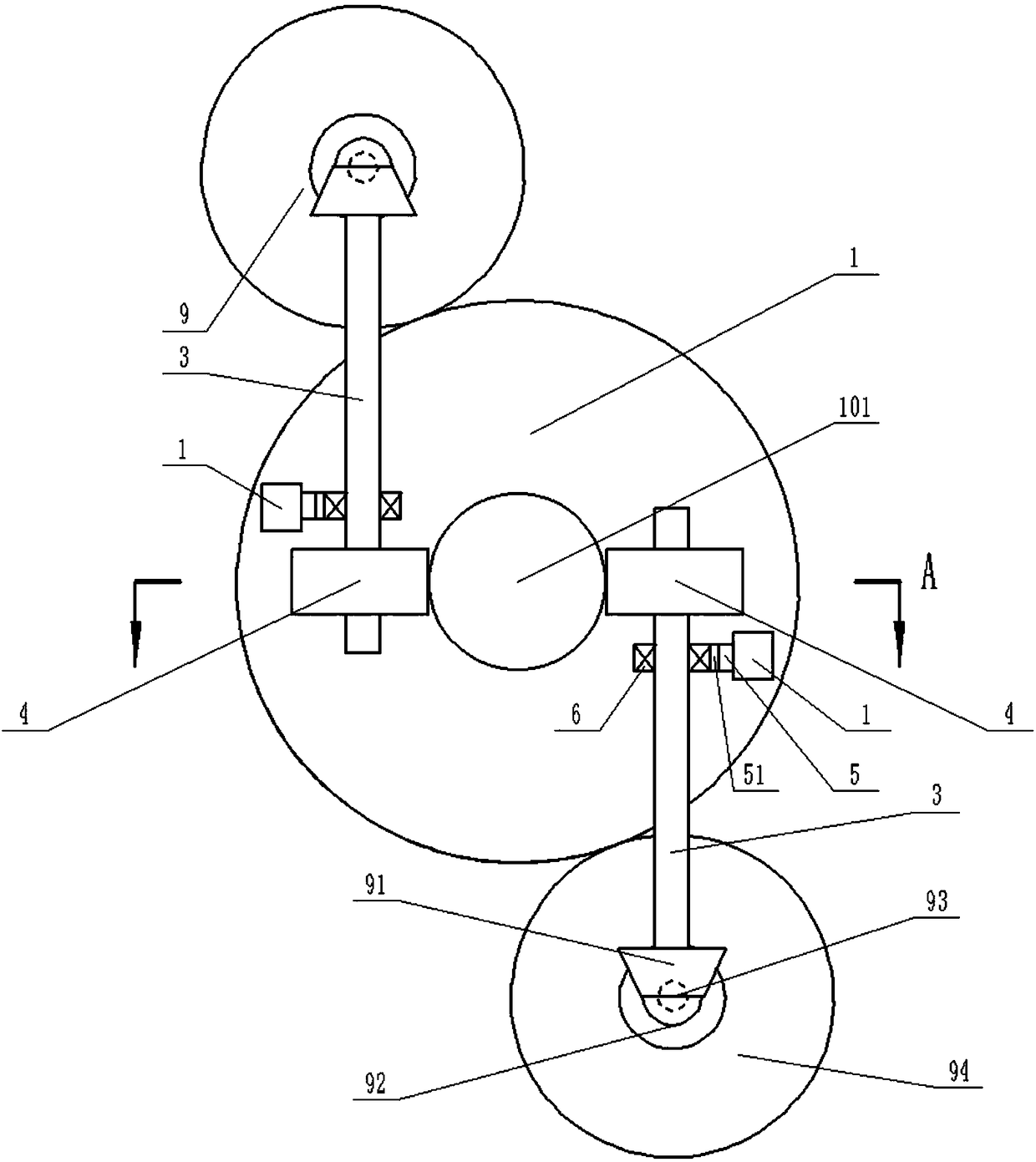
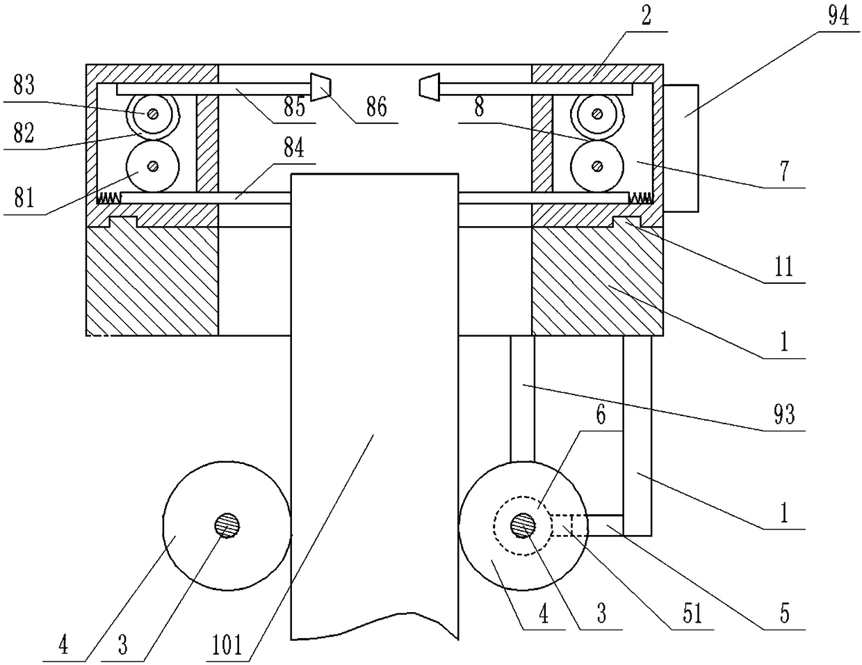
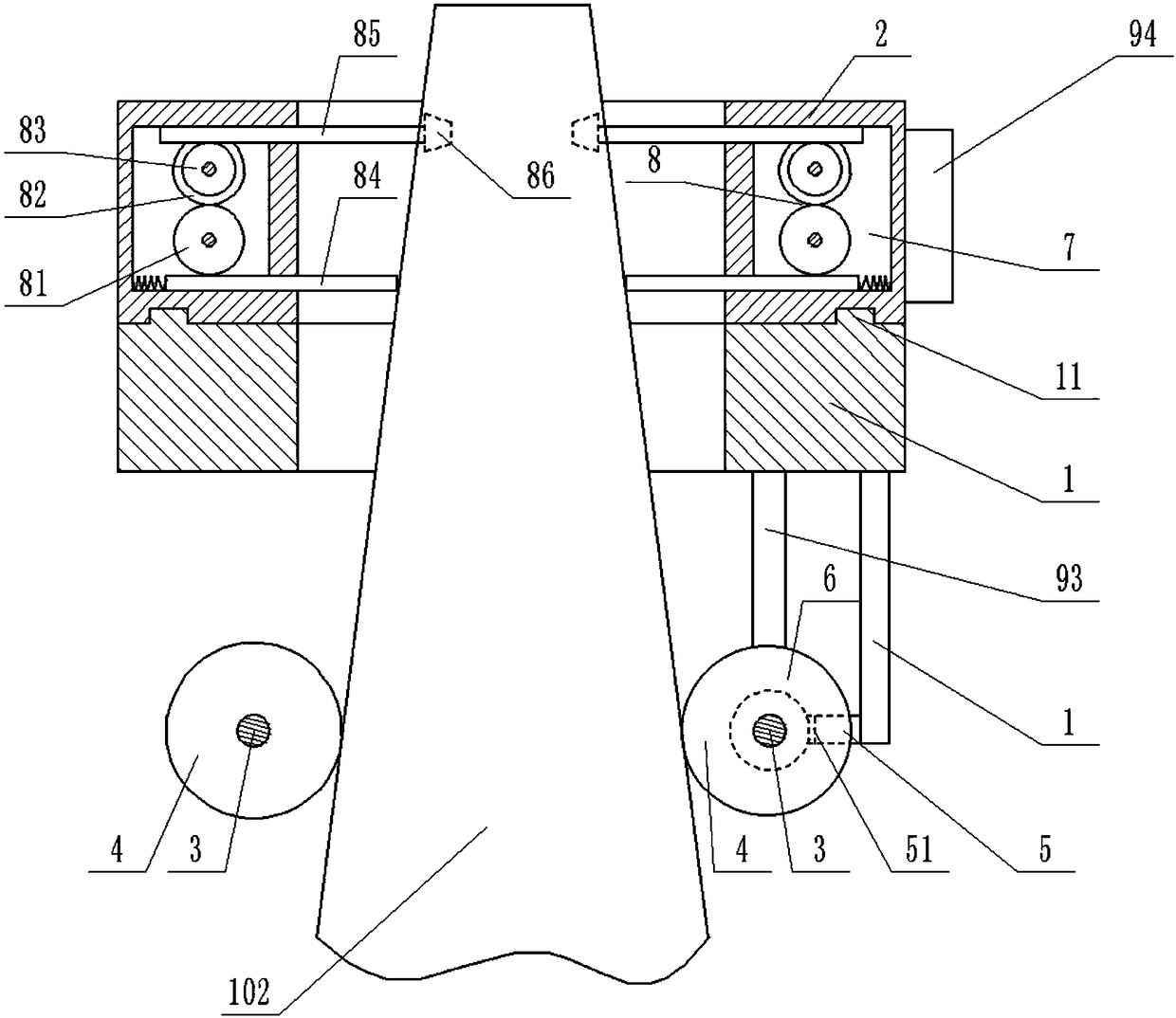
[0032] The reference signs in the drawings of the description include: processing table 1, protrusion 11, first external gear 2, rotating shaft 3, friction wheel 4, telescopic rod 5, telescopic end 51, bearing 6, cavity 7, processing mechanism 8, First gear 81, second gear 82, third gear 83, first rack 84, second rack 85, cutter 86, transmission unit 9, first bevel gear 91, second bevel gear 92, transmission shaft 93, Second external gear 94 , injection molding tube 101 , tapered injection molding tube 102 .

[0033] The embodiment is basically as attached figure 1 , figure 2 As shown: an injection molding pipe processing device, including a cylindrical processing table 1 and a first external gear 2, the processing table 1 is vertically arranged, the first external gear 2 is coaxially connected to the upper end surface of the processing table 1, and the first The lower end surfac...


PUM


Abstract

The invention relates to the technical field of plastic machining, in particular to an injection molding pipe machining device. The device comprises a cylindrical machining table and a first outer gear, the machining table is vertically arranged, the first outer gear is coaxially and rotatably connected to the upper end face of the machining table, two horizontal parallel rotation shafts are arranged below the machining table, and are rotatably connected with the machining table, the two rotation shafts are located on the two sides of the vertical central axis of the machining table, frictionwheels are fixedly connected to the two rotation shafts, a cavity is formed in the first outer gear, and a machining mechanism is arranged in the cavity. According to the injection molding pipe machining device, injection molding pipes of different specifications can be directly machined, and according to the diameter of an injection molding pipe, the cutting depth of a cutter can be adjusted.

Description

technical field [0001] This patent relates to the technical field of plastic processing, in particular to an injection molding pipe processing device. Background technique [0002] The injection molding tube is made by mixing resin powder, stabilizer and other materials, and then crushing to obtain rubber particles, which are finally added to the extrusion injection molding machine. Injection molding pipes have many different diameter specifications, and thread-like grooves need to be processed on the outer surfaces of injection molding pipes of different diameters during production. The method adopted in the prior art is to use a fixture to fix the injection tube on the chuck of the lathe, start the main shaft of the lathe, and the chuck drives the injection tube to rotate. Every time the injection tube rotates with the chuck, the turning tool is evenly moved along the axial direction of the injection tube. Move a lead. In addition, injection molding pipes with larger dia...

Claims


Application Information

Patent Timeline
Patent Type & Authority Applications(China)
IPC IPC(8): B23B5/08B23B25/06
CPCB23B5/08B23B25/06
Inventor 项文增
Owner 宁波高新区新柯保汽车科技有限公司
Why Eureka
Try Eureka