Cutting and grinding integrated machine

A technology of cutting, grinding and all-in-one machine, which is applied in other manufacturing equipment/tools, manufacturing tools, etc., can solve the problems of inability to adjust the cutting width and depth, consume a lot of physical strength, occupy space, etc., and achieve stable structure, stable cutting action, and application wide range of effects

Inactive Publication Date: 2018-06-15
CHIFENG TUOJIA PHOTOELECTRIC CO LTD
View PDF6 Cites 2 Cited by
  • Summary
  • Abstract
  • Description
  • Claims
  • Application Information

AI Technical Summary

Problems solved by technology

[0002] The use of chainsaws to cut materials in various projects can greatly save time and manpower. There are many types of chainsaws on the market. Among them, the double saw blade chainsaw can work conveniently because it does not need to support the workpiece to be cut. And the cutting action is stable and the operation is labor-saving, so it is very popular, but the existing double saw blade structure usually includes a first saw blade and a second saw blade arranged in parallel to each other, and there is a gap between the first saw blade and the second saw blade. The distance of the saw blade and the distance from the saw blade protruding from the chainsaw body are fixed, and the cutting width and depth cannot be adjusted according to actual needs.
[0003] In addition, most of the electric saws in the prior art are dedicated to special machines, special cutting machines or chainsaws are used for cutting materials, and special grinding and polishing machines are used for grinding materials. Therefore, in actual projects, the staff need to carry multiple machines to the construction site. Physically exhausting and takes up space

Method used


Image

  • Cutting and grinding integrated machine
  • Cutting and grinding integrated machine
  • Cutting and grinding integrated machine

Examples


Embodiment 1

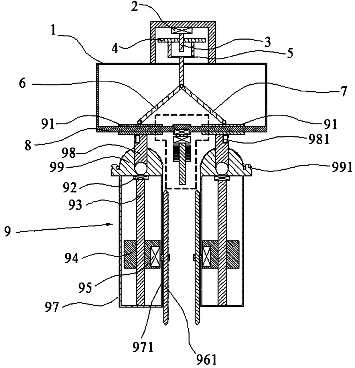
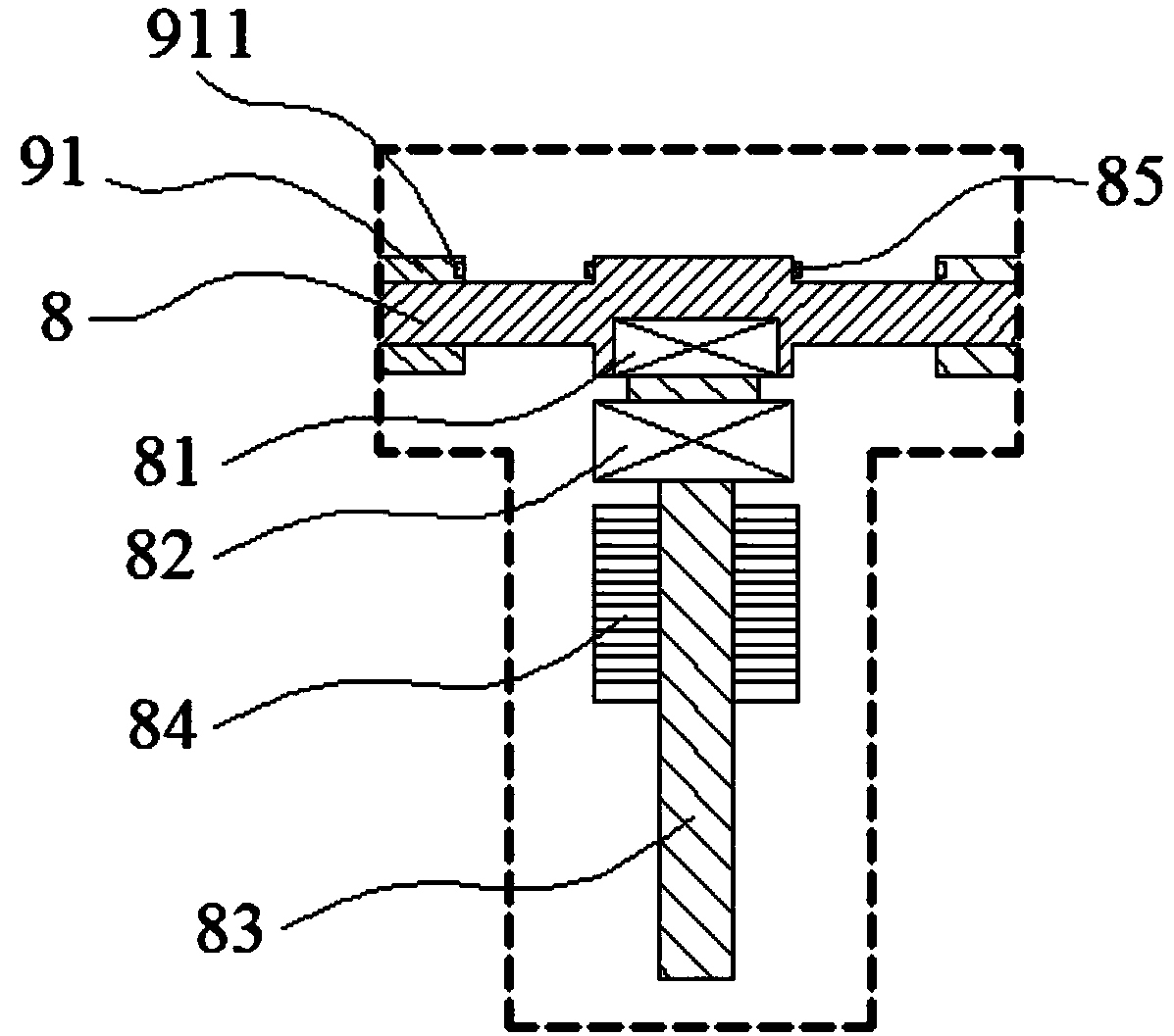
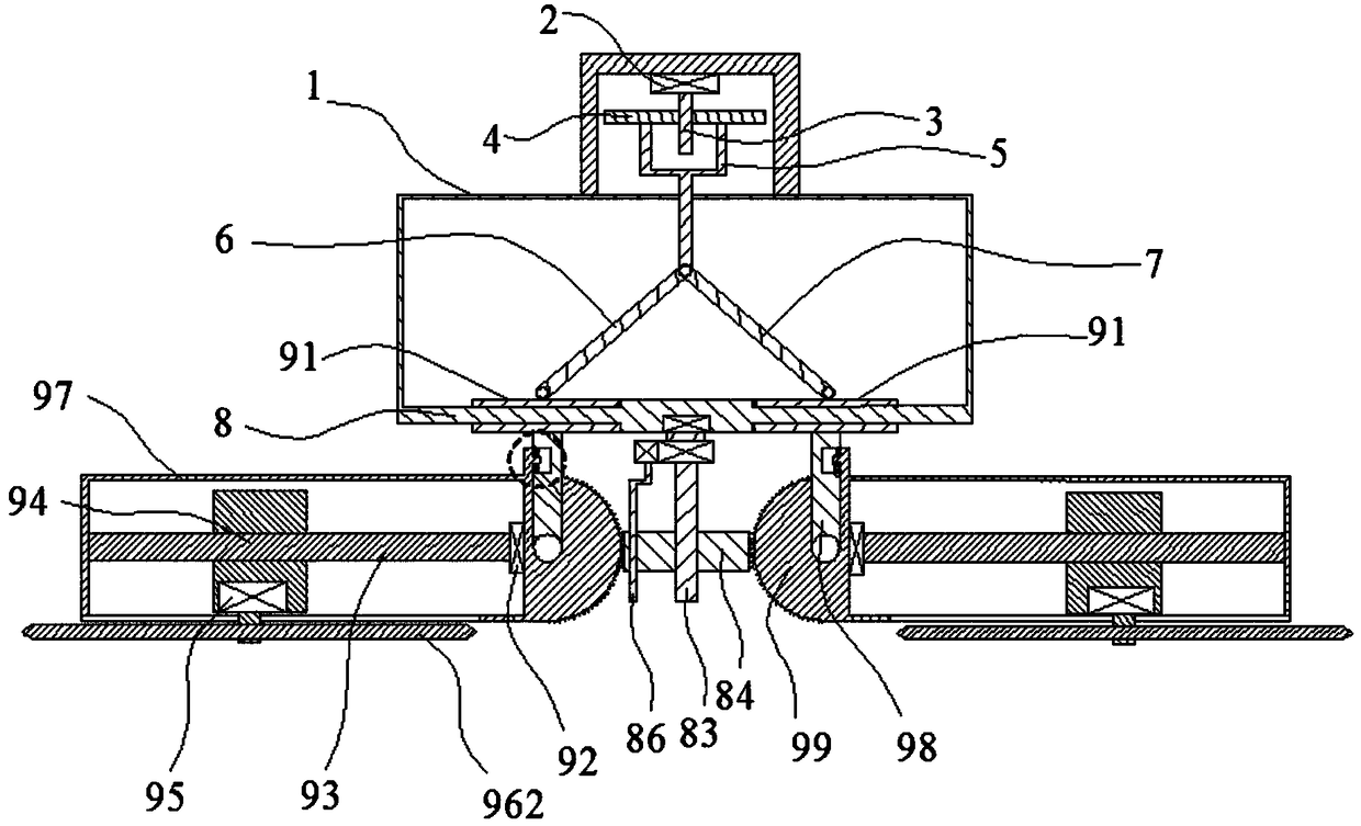
[0037] This embodiment provides an integrated cutting and grinding machine, which includes a housing 1, two sets of mounting bracket assemblies 9 and a direction adjustment mechanism; the lower end of the housing 1 is provided with a sliding rod 8, and two The third slide block 91, the lower ends of the two third slide blocks 91 are provided with support rods 98, and the lower ends of the support rods 98 are all movably connected to the mounting frame assembly 9, and two groups of mounting frame assemblies 9 are symmetrically arranged, and the upper ends of each group of mounting frame assemblies 9 The end face of the limiting end 99 is arc-shaped and provided with gear teeth. The middle part of the slide bar 8 is provided with a direction adjustment mechanism, which includes a fifth slide block 84 that slides up and down and is located in two sets of mounting bracket assemblies. 9, both ends of the fifth sliding block 84 have gear teeth meshing with the end surface of the limi...

Embodiment 2

[0039] Such as Figure 1-4As shown, this embodiment provides an integrated cutting and grinding machine, which includes a housing 1, two sets of mounting bracket assemblies 9 and a direction adjustment mechanism; Two third slide blocks 91 are established, and the lower ends of the two third slide blocks 91 are provided with support rods 98, and the lower ends of the support rods 98 are movably connected to the mounting frame assemblies 9, and two groups of mounting frame assemblies 9 are arranged symmetrically, each group of mounting frame assemblies The end face of the limiting end 99 at the upper end of 9 is arc-shaped and is provided with gear teeth. The middle part of the slide bar 8 is provided with a direction adjustment mechanism. The direction adjustment mechanism includes a fifth slider 84 that slides up and down and is located in two Between the mounting frame assembly 9 , both ends of the fifth sliding block 84 have gear teeth engaged with the end faces of the limit...

Embodiment 3

[0041] Such as Figure 1-4 As shown, this embodiment provides an integrated cutting and grinding machine, which includes a housing 1, two sets of mounting bracket assemblies 9 and a direction adjustment mechanism; Two third slide blocks 91 are established, and the lower ends of the two third slide blocks 91 are provided with support rods 98, and the lower ends of the support rods 98 are movably connected to the mounting frame assemblies 9, and two groups of mounting frame assemblies 9 are arranged symmetrically, each group of mounting frame assemblies The end face of the limiting end 99 at the upper end of 9 is arc-shaped and is provided with gear teeth. The middle part of the slide bar 8 is provided with a direction adjustment mechanism. The direction adjustment mechanism includes a fifth slider 84 that slides up and down and is located in two Between the mounting frame assembly 9 , both ends of the fifth sliding block 84 have gear teeth engaged with the end faces of the limi...


PUM


Abstract

The invention provides a cutting and grinding integrated machine which comprises a shell, two mounting frame assemblies and a direction adjusting mechanism. A sliding rod is arranged on the lower endface of the shell, and sleeved with two third sliding blocks. The lower ends of the two third sliding blocks are provided with supporting rods correspondingly, and the lower ends of the supporting rods are movably connected with the mounting frame assemblies correspondingly. The two mounting frame assemblies are symmetrically arranged, and the end face of the limiting end of the upper end of eachmounting frame assembly is in a circular arc shape and is provided with gear teeth. The direction adjusting mechanism is arranged in the middle of the sliding rod, and comprises fifth sliding blocks which vertically slide and are located between the two mounting frame assemblies. The two ends of the fifth sliding blocks are provided with gear teeth engaged with the end faces of the limiting ends.By using the cutting and grinding integrated machine, the function of cutting or grinding can be switched according to the need, the effect that one machine has multiple purposes is achieved, and theflexibility, convenience and rapidness are achieved.

Description

technical field [0001] The invention relates to a cutting and polishing integrated machine. Background technique [0002] The use of chainsaws to cut materials in various projects can greatly save time and manpower. There are many types of chainsaws on the market. Among them, the double saw blade chainsaw can work conveniently because it does not need to support the workpiece to be cut. And the cutting action is stable, and the operation is labor-saving, so it is very popular, but the existing double saw blade structure usually includes a first saw blade and a second saw blade arranged in parallel to each other, and there is a gap between the first saw blade and the second saw blade. The distance of the saw blade and the distance that the saw blade protrudes from the chainsaw body are fixed, and the cutting width and depth cannot be adjusted according to actual needs. [0003] In addition, most of the electric saws in the prior art are dedicated to special machines, special...

Claims


Application Information

Patent Timeline
Patent Type & Authority Applications(China)
IPC IPC(8): B23P23/04
Inventor 李梅
Owner CHIFENG TUOJIA PHOTOELECTRIC CO LTD
Why Eureka
Try Eureka