
Control method for supporting dynamic coupling and decoupling of train

A control method and linking technology, applied in the directions of signal indicators, automatic systems, transportation and packaging, etc. on the vehicle, can solve problems such as train position calculation errors, failure to support train dynamic linking and unpacking operations, safety issues, etc. achieve the effect of improving operational efficiency

Active Publication Date: 2018-06-15
CASCO SIGNAL
View PDF3 Cites 22 Cited by
  • Summary
  • Abstract
  • Description
  • Claims
  • Application Information

AI Technical Summary

Problems solved by technology

[0005] However, one of the reasons why the above-mentioned operation mode cannot be implemented is that the existing urban rail transit train control system does not support the dynamic connection and decommissioning of trains, that is, it is required that the formation of operating trains must be fixed
The reason is that in the on-board controller, parameter information such as the length of the train and the distance from the transponder antenna to the front of the car needs to be stored in advance, which cannot be changed during operation
If the train formation has changed, the data of the on-board controller must be reprogrammed to ensure that the information used in the controller is consistent with the actual train, otherwise it will lead to wrong calculation of the train position and cause serious safety problems

Method used


Image

  • Control method for supporting dynamic coupling and decoupling of train
  • Control method for supporting dynamic coupling and decoupling of train
  • Control method for supporting dynamic coupling and decoupling of train

Examples


Embodiment Construction

[0040] The following will clearly and completely describe the technical solutions in the embodiments of the present invention with reference to the drawings in the embodiments of the present invention. Obviously, the described embodiments are part of the embodiments of the present invention, not all of them. Based on the embodiments of the present invention, all other embodiments obtained by persons of ordinary skill in the art without making creative efforts shall fall within the protection scope of the present invention.

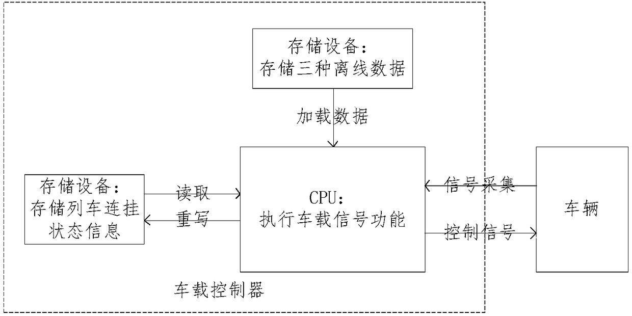
[0041] Such as figure 1 As shown, a structure of an on-board controller that supports dynamic connection and decompilation of trains includes a storage device for storing state information of train connections; a medium FLASH for storing three kinds of offline data; and a CPU for performing on-board signal functions.

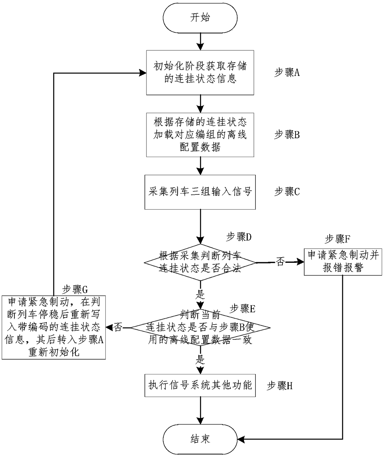
[0042] Such as figure 2 Shown, the work flowchart of the present invention is described in detail as follows:

[0043] Step A: Obtain th...


PUM


Abstract

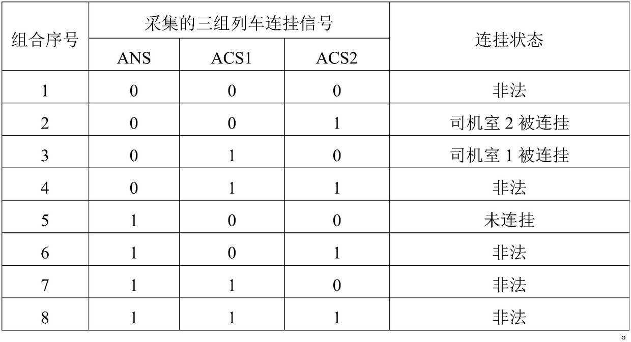
The invention relates to a control method for supporting dynamic coupling and decoupling of a train. The control method comprises the steps that A, at the initialization stage, stored coupling state information is obtained; B, offline configuration of a corresponding group is loaded according to the stored coupling state; C, three sets of input signals related to coupling are collected; D, according to the collected signals, whether the coupling state of the train is legal or not is judged, if the coupling state of the train is legal, the step E is executed, and if the coupling state of the train is illegal, the step F is executed; E, whether the current coupling state is consistent with the offline configuration used in the step B or not is judged, and if the current coupling state is consistent with the offline configuration used in the step B, the step H is executed, and if the current coupling state is not consistent with the offline configuration used in the step B, the step G isexecuted; F, emergency braking is applied, and error reporting alarming is conducted; and G, emergency braking is applied, after the situation that the train is stably parked is judged, coupling stateinformation with codes is repeatedly written in, and then the step A is executed for re-initialization. Compared with the prior art, the control method has the advantages of high safety, high reliability, high automation degree and the like.

Description

technical field [0001] The invention relates to the field of urban rail traffic signal control, in particular to a control method supporting dynamic train connection and decoupling. Background technique [0002] The passenger flow of urban rail transit lines is usually unevenly distributed in time, and there are obvious passenger flow peaks during commuting and commuting on weekdays. In order to keep the platform at the destination of passengers as soon as possible, more trains need to be put into operation during peak hours to improve operational capacity; while in other periods, the number of operating trains is generally reduced to avoid waste of resources caused by running empty trains. However, this mode of operation will lead to long waiting times for passengers during non-peak hours and a decrease in satisfaction. [0003] In addition, in order to solve the problem of uneven distribution of passenger flow in the lines connecting suburban new cities and the city cente...

Claims


Application Information

Patent Timeline
IPC IPC(8): B61L15/00
CPCB61L15/0054B61L15/0018B61L15/0072B61G7/00B61L15/0081B61L27/04B61L2201/00
Inventor 方兴常鸣吕新军
Owner CASCO SIGNAL
Learn More