
Pivoted bridge pivot body device

A swivel and bridge technology, which is applied in the field of swivel bridges, can solve the problems of increasing the difficulty of maintenance and dismantling of swivel bridges, prone to safety accidents, and turning to the construction site, etc., so as to shorten the closing time, simplify construction, avoid effect of influence

Pending Publication Date: 2018-06-15
CHINA RAILWAY DESIGN GRP CO LTD +1
View PDF5 Cites 2 Cited by
  • Summary
  • Abstract
  • Description
  • Claims
  • Application Information

AI Technical Summary

Problems solved by technology

However, in the prior art, the swivel support can only rotate the bridge from the construction site to the working site. When the bridge needs to be repaired or removed after a period of use, the bridge cannot be rotated from the working site to the construction site. site, increasing the difficulty of maintenance and dismantling of the swivel bridge, increasing maintenance costs, and prone to safety accidents

Method used


Image

  • Pivoted bridge pivot body device
  • Pivoted bridge pivot body device
  • Pivoted bridge pivot body device

Examples


Embodiment Construction

[0026] Other objects and advantages of the present invention will become clear by explaining the following preferred embodiments of the present application.

[0027] Various exemplary embodiments of the present invention will now be described in detail. The detailed description should not be considered as a limitation of the present invention, but rather as a more detailed description of certain aspects, features and embodiments of the present invention.

[0028] It should be understood that the terminology described in the present invention is only used to describe specific embodiments, and is not used to limit the present invention. In addition, regarding the numerical ranges in the present invention, it should be understood that each intermediate value between the upper limit and the lower limit of the range is also specifically disclosed. Each smaller range between any stated value or intervening value in a stated range and any other stated value or intervening value in a ...


PUM


Abstract

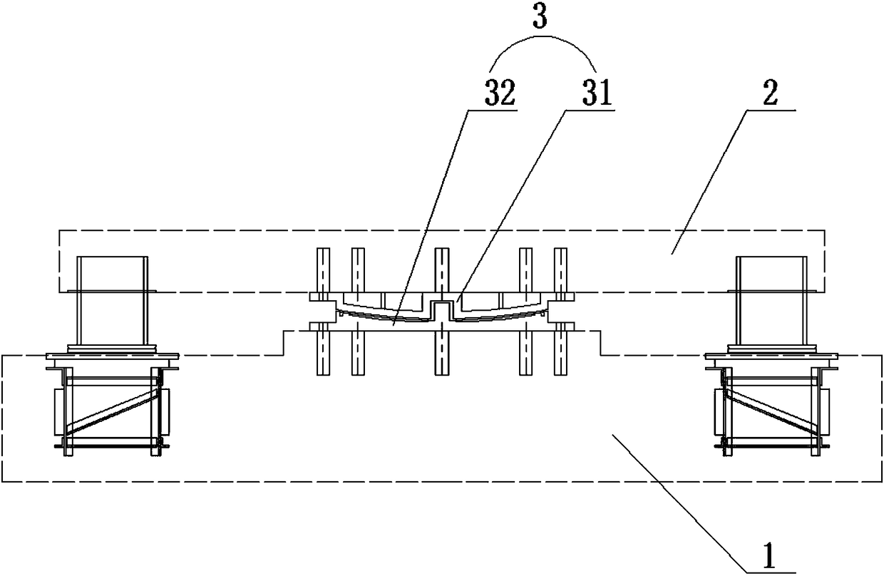
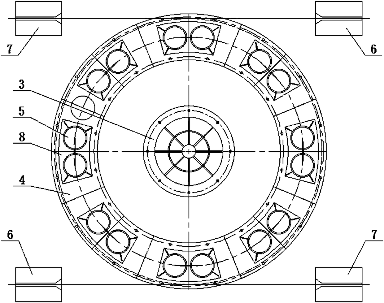
Provided is a pivoted bridge swivel body device. The device comprises a pivot body support base, an annular slide track, multiple support feet, a first traction unit and a second traction unit; the pivot body support base comprises a lower spherical pendulum and an upper spherical pendulum which are fixed to a fixed part of a pivot body bridge and a rotary part of the pivot body bridge respectively; the annular slide track is fixed to the upper surface of the fixed part; the support feet are fixed to the lower portions of the rotary part and can slide on the annular slide track; the first traction unit drives the rotary part to rotate clockwise by exerting action force which can make the rotary part capable of sliding on the annular slide track clockwise on the rotary part through a traction cable; the second traction unit drives the rotary part to rotate anticlockwise by exerting action force which can make the rotary part capable of sliding on the annular slide track anticlockwise onthe rotary part through a traction cable. The pivoted bridge swivel body device can make the pivot body bridge capable of not only pivoting from a construction site to a work site but also pivoting back to the construction site from the work site, and thus the maintenance of the pivot body bridge is facilitated.

Description

technical field [0001] The present invention generally relates to the field of swivel bridges, and in particular to a swivel device of a swivel bridge, specifically a swivel bridge swivel device. Background technique [0002] The swivel bridge is a bridge constructed by the swivel method. Specifically, it refers to the construction of bridge parts that cross rivers, roads, and railways on both banks or both sides of the road. The rotation of the beam body on both sides reaches the working position of the bridge, and at the working position, the two parts are closed to form a whole bridge. The bridge swivel technology can convert the operation above the obstacle into the operation on the shore or near the ground, which can not only ensure the safety of the project construction, but also reduce the impact on traffic, shorten the closure time, and reduce the construction cost. [0003] The swivel bridge is driven by the rotation of the swivel support from the construction site...

Claims


Application Information

Patent Timeline
IPC IPC(8): E01D21/08
CPCE01D21/08
Inventor 田山坡魏毅强张伟康曹全宋顺心侯春辉刘涛王彦支燕武杨根杰王菲王思宇王希慧桂鉴臣张兴魏春晶王念才
Owner CHINA RAILWAY DESIGN GRP CO LTD
Learn More