Supercharge Your Innovation With Domain-Expert AI Agents!

Device and method for movably dismantling suspended ceiling

A technology for removable and suspended ceilings, which is applied to ceilings, building components, buildings, etc., and can solve problems such as inconvenience, unreliable connection between suspended ceilings and suspender rods, and easy falling of suspended ceilings

Pending Publication Date: 2018-06-15
SHIJIAZHUANG CHANGHONG BUILDING DECORATION ENG
View PDF0 Cites 0 Cited by
  • Summary
  • Abstract
  • Description
  • Claims
  • Application Information

AI Technical Summary

Problems solved by technology

[0002] At present, there are air-conditioning or fire-fighting pipes above the suspended ceiling, but in the prior art, the suspended ceiling is often fixedly connected with the suspenders fixed on the roof, so that when the air-conditioning or fire-fighting pipes need to be repaired, the maintenance work is inconvenient because the suspended ceiling cannot be disassembled
In addition, the connection between the suspended ceiling and the suspender rod is not firm, which makes the suspended ceiling easy to fall.

Method used


Image

  • Device and method for movably dismantling suspended ceiling
  • Device and method for movably dismantling suspended ceiling
  • Device and method for movably dismantling suspended ceiling

Examples


Embodiment 1

[0028] Embodiment 1 A device for movable and dismantling a suspended ceiling

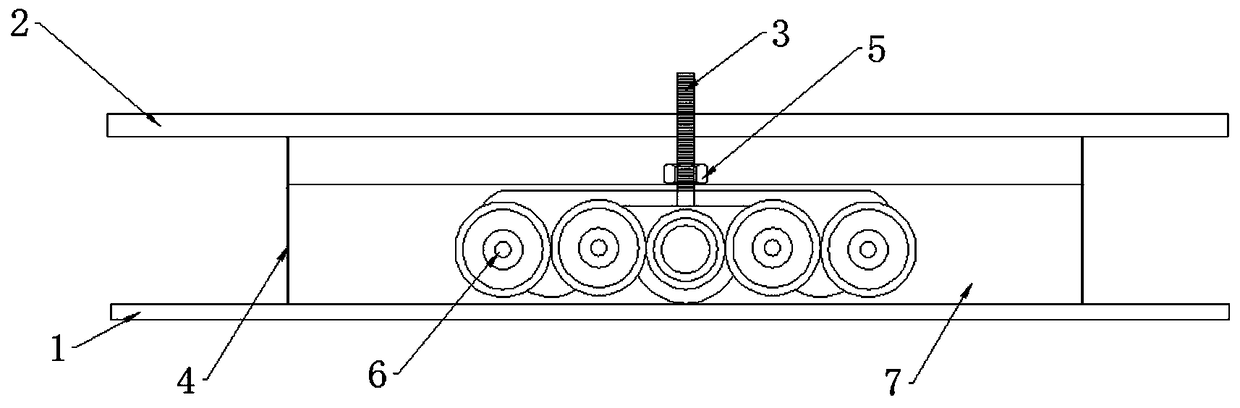
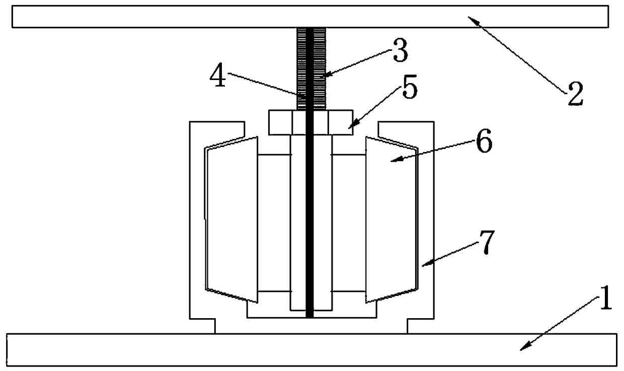
[0029] Such as Figure 1-3 As shown, this embodiment includes a suspender 3 placed between the suspended ceiling 1 and the roof 2 , a dismantling mechanism, and a wire rope 4 . Suspended ceiling 1 is the hidden layer of indoor electrical, ventilation and air-conditioning, communication or fire protection, alarm pipeline equipment and other projects. Suspended ceiling 1 can adopt aluminum boards, wooden boards or plates of other materials.

[0030] The suspension rod 3 is a threaded rod, the upper end is fixed on the roof 2, and the lower end is threadedly connected with the dismounting mechanism.

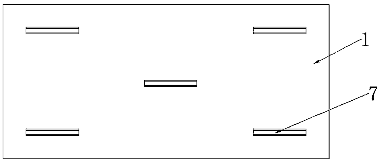
[0031] The dismounting mechanism is a sliding mechanism that can make the suspended ceiling 1 slide relative to the fixed boom 3 . The sliding mechanism includes a sliding track 7 and a hanging wheel 6 . The hanging wheel 6 is placed in the sliding track 7 and is slidably connected with the sliding tra...

Embodiment 2

[0036] Embodiment 2 A method for removing the suspended ceiling

[0037] This embodiment is realized by utilizing the device for movable and dismounting the suspended ceiling in Embodiment 1. Include the following steps:

[0038] (A), untie the wire rope 4 tied between the roof 2 and the suspended ceiling 1;

[0039] (B), first turn the nut 5 on the suspender 3, so that the suspension wheel 6 can slide on the sliding track 7; then slide the suspension wheel 6 along the sliding track 7 to break away from the sliding track 7, so that the ceiling 1 is removed from the lower end of the suspender ;

[0040] The above steps can be performed first (A) and then (B), or (A) and then (B), or at the same time.


PUM


Abstract

The invention discloses a device and method for movably dismantling a suspended ceiling. The device for movably dismantling the suspended ceiling comprises a suspended rod which is arranged between the suspended ceiling and a roof, a dismantling mechanism capable of dismantling the suspended ceiling is arranged between the suspended rod and the suspended ceiling, and a steel wire rope which makesthe suspended ceiling suspended on the roof is arranged between the roof and the suspended ceiling. The method for movably dismantling the suspended ceiling is implemented through the device for movably dismantling the suspended ceiling. The method comprises the following steps of A, untying the steel wire rope which is tied between the roof and the suspended ceiling; B, dismantling the suspendedceiling from the lower end of the suspended rod through the dismantling mechanism. By means of the device and method for movably dismantling the suspended ceiling, the suspended ceiling can be detachably connected with the suspended rod, and an air conditioner or a firefighting pipe is conveniently overhauled. The device and method are applicable to the portion between the suspended ceiling and the roof, and are used for dismantling the suspended ceiling.

Description

technical field [0001] The invention belongs to the technical field of building decoration, and relates to a decorative partition, in particular to a device and method for movably dismantling a suspended ceiling. Background technique [0002] At present, there are air-conditioning or fire-fighting pipes above the suspended ceiling, but in the prior art, the suspended ceiling is often fixedly connected with the suspenders fixed on the roof, so that when the air-conditioning or fire-fighting pipes need to be repaired, the maintenance work is inconvenient because the suspended ceiling cannot be disassembled . In addition, the connection between the suspended ceiling and the suspender rod is not firm, so that the suspended ceiling is easy to fall. Contents of the invention [0003] In order to solve the above disadvantages in the prior art, the present invention aims to provide a device and method for movably dismantling the suspended ceiling, so as to achieve the purpose of ...

Claims


Application Information

Patent Timeline
Patent Type & Authority Applications(China)
IPC IPC(8): E04B9/18E04B9/22
CPCE04B9/18E04B9/22
Inventor 蔡文才陈元明陈雪亮张芹德姜飞
Owner SHIJIAZHUANG CHANGHONG BUILDING DECORATION ENG
Features
  • R&D
  • Intellectual Property
  • Life Sciences
  • Materials
  • Tech Scout
  • Unparalleled Data Quality
  • Higher Quality Content
  • 60% Fewer Hallucinations
Learn More