Accommodating structure, probe housing method and biochemical analyzer

A technology for biochemical analyzers and accommodating structures, applied in the field of biochemical analyzers, can solve the problems of easy accidental injury, no protection, easy damage or dislocation of operators, and achieve the effect of preventing accidental damage

Pending Publication Date: 2018-06-15
深圳市普康电子有限公司
0 Cites 0 Cited by

AI-Extracted Technical Summary

Problems solved by technology

At present, when the automatic biochemical analyzer is powered off according to the normal shutdown process, the sample needle, reagent needle and stirring rod are above the cleaning position and are in an unprotected state, and the operator is easily injured ...

Method used

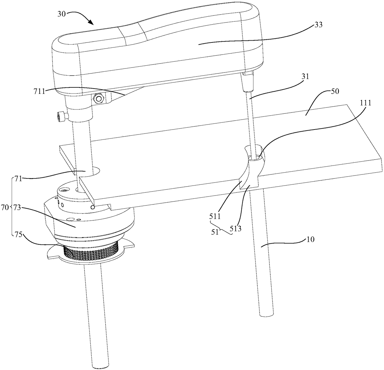
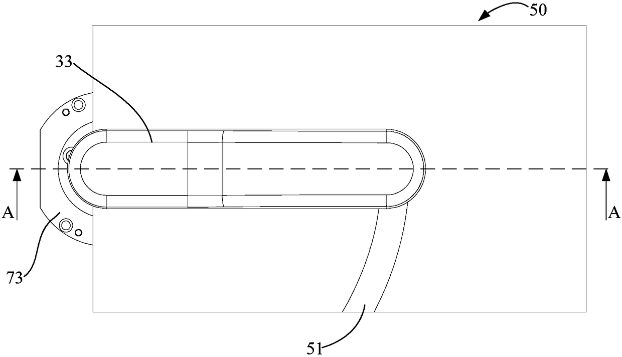
Referring to Fig. 1 to Fig. 3, further, housing 50 is also concavely provided with guide groove 51, and described guide groove 51 extends along horizontal direction, and communicates with described accommodating chamber 11, and described probe assembly 30 is opposite When the casing 50 moves, a part of the probe 31 moves along the extending direction of the guide groove 51 and extends into the receiving cavity 11 from the opening 111 . The guide groove 51 is provided to protect the probe 31 during the movement of the probe 31 to the receiving cavity 11 , preventing the user from hitting the probe 31 during the movement and causing the probe 31 to be damaged. The guide groove 51 includes a bottom wall 513 and a side wall 511 connected to the bottom wall 513. It can be understood that the bottom wall 513 of the opening of the accommodating cavity communicates with the guide groove 51 and the accommodating cavity, or the bottom of the guide groove 51 is provided with There is a through hole, which communicates with the opening. Such setting is convenient for the probe 31 to be inserted into the accommodating cavity after moving in the guide groove 51 , so as to protect the probe 31 conveniently.
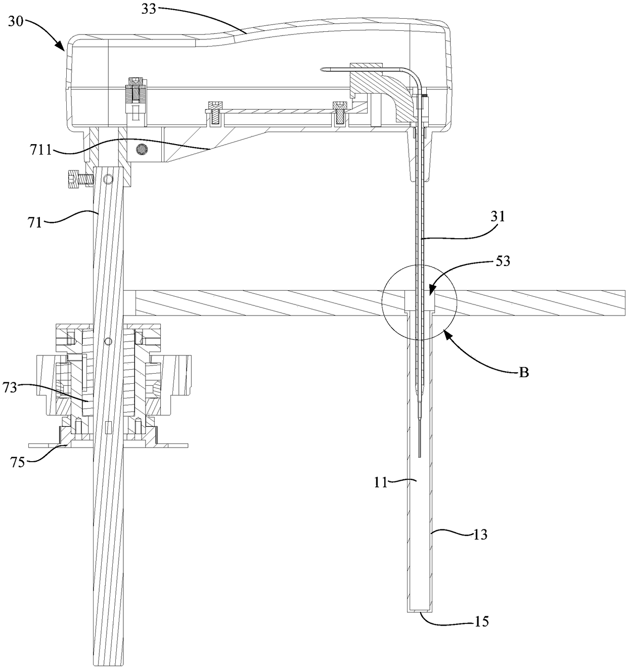
Referring to Fig. 3, further, accommodating structure 10 comprises side plate 13 and the bottom plate 15 that is connected with side plate 13, and described side plate 13 and described bottom plate 15 form described accommodating cavity 11 jointly, and described accommodating cavity 11 The opening 111 is set facing the bottom plate 15 . The accommodating cavity 11 is formed by arranging the bottom plate 15 and the side plate 13 , which is convenient for accommodating the probes 31 , and the opening 111 is facing the bottom plate 15 , so that the probes 31 can be directly protected after being inserted into the accommodating cavity 11 . In this embodiment, the shape of the accommodating cavity 11 may be a cylinder, a triangular prism, a quadrangular prism or other shapes. Preferably, the shape of the accommodating cavity 11 is a cylinder. It can be understood that the extension direction of the accommodation cavity 11 is perpendicular to the plane on which the probe arm 33 rotates, that is, the accommodation cavity 11 is perpendicular to the plane, so that the probe 31 is conveniently accommodated in the accommodation cavity 11, so that the probe 31 for better protection. Bottom plate 15 and side plate 13 can be integrally formed, also can be set separately, and the present invention adopts the mode that bottom plate 15 and side plate 13 are integrally formed, such setting is convenient for production.
[0033] The technical solution of the present invention is provided with the accommodating cavity 11. When the probe 31 needs to be protected, the probe assembly 30 moves relative to the housing 50, and the part of the probe 31 is inserted into the accommodating cavity 11 through the opening 111, thereby The probe 31 will not be damage...

Abstract

The invention discloses an accommodating structure, a probe housing method and a biochemical analyzer. The accommodating structure is used for the biochemical analyzer, the biochemical analyzer comprises a probe component and a shell, the probe component and the shell are in flexible connection, the probe component includes a probe, the accommodating structure includes an accommodating cavity, anopening is formed on the accommodating cavity, the probe component moves relative to the shell, and part of the probe stretches into the accommodating cavity through the opening. The technical schemeadopted by the invention aims to provide protection for sample needles, reagent needles and stirring rods to prevent accidental damage of users or the biochemical analyzer.

Application Domain

Technology Topic

Image

  • Accommodating structure, probe housing method and biochemical analyzer
  • Accommodating structure, probe housing method and biochemical analyzer
  • Accommodating structure, probe housing method and biochemical analyzer

Examples

  • Experimental program(1)

Example Embodiment

[0028] The technical solutions in the embodiments of the present invention will be clearly and completely described below in conjunction with the accompanying drawings in the embodiments of the present invention. Obviously, the described embodiments are only a part of the embodiments of the present invention, rather than all the embodiments. Based on the embodiments of the present invention, all other embodiments obtained by those of ordinary skill in the art without creative work shall fall within the protection scope of the present invention.
[0029] It should be noted that all the directional indications (such as up, down, left, right, front, back...) in the embodiments of the present invention are only used to explain the difference between components in a specific posture (as shown in the accompanying drawings). If the relative positional relationship, movement situation, etc. change, the directional indication will change accordingly.
[0030] In addition, the descriptions related to "first", "second", etc. in the present invention are only for descriptive purposes, and cannot be understood as indicating or implying their relative importance or implicitly indicating the number of indicated technical features. Therefore, the features defined with "first" and "second" may explicitly or implicitly include at least one of the features. In addition, the technical solutions between the various embodiments can be combined with each other, but they must be based on what can be achieved by those of ordinary skill in the art. When the combination of technical solutions is contradictory or cannot be achieved, it should be considered that such a combination of technical solutions does not exist. , Is not within the protection scope of the present invention.
[0031] The present invention proposes a containing structure 10.
[0032] Reference Figure 1 to Figure 5 The accommodating structure 10 proposed by the technical solution of the present invention is used for a biochemical analyzer (not shown), the biochemical analyzer includes a probe assembly 30 and a housing 50, and the probe assembly 30 is movably connected to the housing 50 The probe assembly 30 includes a probe 31, the accommodating structure 10 includes an accommodating cavity 11, the accommodating cavity 11 is formed with an opening 111, and the probe assembly 30 moves relative to the housing 50 to remove the probe Part of the needle 31 extends into the receiving cavity 11 through the opening 111.
[0033] The technical solution of the present invention is to provide the accommodating cavity 11, when the probe 31 needs to be protected, the probe assembly 30 moves relative to the housing 50 to extend the part of the probe 31 into the accommodating cavity 11 through the opening 111, so that the probe 31 will not be damaged due to the impact, thereby protecting the probe assembly 30. In this way, the technical solution of the present invention can provide protection for the sample needle, the reagent needle and the stirring rod to prevent accidental damage to the user or the biochemical analyzer.
[0034] Reference figure 1 , image 3 In this embodiment, the biochemical analyzer further includes a rotating assembly 70 and a driving assembly (not shown). The rotating assembly 70 is fixedly connected to the probe assembly 30 and controls the probe assembly 30 to face each other. The housing 50 rotates to make the probe 31 face the opening 111, the drive assembly is fixedly connected to the probe assembly 30, and the probe assembly 30 is controlled to move in the vertical direction relative to the housing 50 , The probe 31 is contained in the containing cavity 11.
[0035] The probe assembly 30 further includes a probe arm 33, and the probe 31 is fixed to the side surface of one end of the probe arm 33. The probe arm 33 is used to improve the detection efficiency of the probe 31 and can detect more samples; the rotating assembly 70 also includes a support rod 71, a rotating member 73 and a code disc 75, and the support rod 71 is fixed to the other end of the probe arm 33 The support rod 71 is provided on the side surface of the sensor to facilitate the control of the probe arm 33, thereby facilitating the use of the biochemical analyzer. The supporting rod 71 is also sleeved with a rotating member 73 and a code disc 75, which is fixedly connected to the supporting rod 71. The code disc 75 is used to accurately determine the rotation angle of the probe 31, and the rotating member 73 can be a variable speed gear. The support rod 71 is driven to rotate, and the rotation rate of the code disc 75 and the support rod 71 is adjusted. It is understandable that the surface of the support rod 71 is protruding with convex keys, the inner side of the wheel code plate 75 is provided with grooves, and the support rod 71 and the rotating member 73 are fixedly connected by the engagement of the ribs and the grooves. Of course, The two can be fixedly connected by welding, as long as the two can be fixed well. And the support rod 71 also includes a rib 711, which is provided at the junction of the support rod 71 and the probe arm 33. The rib 711 can make the probe arm 33 and the support rod 71 have better structural strength. Prevent the probe 31 from being damaged.
[0036] And, both the code disc 75 and the rotating member 73 are provided with a through hole (not shown), and a screw connection piece (not shown) is installed in the through hole to fix the code plate 75 and the rotating member 73. Specifically, the screw The connecting piece can be a screw or a screw. In order to facilitate the rotation of the rotating member 73, a bearing (not shown) may also be provided on the rotating member 73 and fixed to the housing 50. This arrangement allows the rotating member 73 to rotate smoothly, thereby driving the probe 31 to rotate smoothly. In addition, the biochemical analyzer also includes a stepping motor (not shown). The stepping motor is connected to the code disk 75, drives the code disk 75 to rotate, and then drives the rotating member 73 to drive the support rod 71 to rotate to realize the probe assembly The 30 rotates relative to the housing 50, and the probe 31 is transported to the opening 111 of the containing cavity 11 through the control system.
[0037] In this embodiment, the driving assembly may be a cylinder, and the entire probe assembly 30 is driven to move up and down relative to the housing 50 through the cylinder; of course, in order to make the probe assembly 30 move up and down relative to the housing 50, the support rod 71 It also has a telescopic rod. When the probe 31 is transported to the opening 111, the biochemical analyzer controls the rod to contract, so that the probe assembly 30 can move up and down relative to the housing 50.
[0038] Further, the containing structure 10 and the housing 50 are integrally provided. The integrally arranged structure is convenient for processing and molding, and the connection between the two is excessively smooth, which will not adversely affect the extension and storage of the probe 31, thereby achieving better protection for the probe 31.
[0039] Reference Figure 4 In this embodiment, the containing structure 10 and the housing 50 are detachably connected. The detachable connection facilitates the cleaning of the containing structure 10 and the cleaning of the containing structure 10, and it is convenient to replace the probe 31 because the containing structure 10 protects the probe 31 from damage.
[0040] Further, in order to realize a detachable connection between the accommodating structure 10 and the housing 50, in this embodiment, the housing 50 is formed with a stepped hole 53 penetrating therethrough, and the stepped hole 53 includes a large aperture section 531 and A small-aperture section 533, the small-aperture section 533 is disposed adjacent to the accommodating cavity 11, the accommodating structure 10 forms a boss 17 at the opening 111 of the accommodating cavity 11, and the boss 17 is clamped in the large-aperture section 531 and the small aperture section 533; it is understandable that in this embodiment, the accommodating structure 10 and the housing 50 are detachably connected, which can also be realized by other connection methods, as an optional implementation of the embodiment Mode, the housing 50 is provided with a threaded hole (not shown) therethrough, the containing structure 10 is provided with an external thread (not shown) at the opening 111 of the containing cavity 11, and the containing structure 10 is detachable through a threaded connection Connected to the housing 50; or, the housing 50 is provided with a through hole (not shown), the hole section of the escape hole is recessed with a groove (not shown), the containing structure 10 An elastic convex ring (not shown) is provided at the opening 111 of the accommodating cavity 11, and the elastic convex ring extends into the relief hole and is detachably contained in the groove. Of course, the detachable connection of the present invention is not limited to the above three connection methods, and can also be realized by detachable connection methods such as a buckle structure and a plug pin, as long as the detachable connection can be better realized.
[0041] Reference image 3 Further, the containing structure 10 includes a side plate 13 and a bottom plate 15 connected to the side plate 13. The side plate 13 and the bottom plate 15 together form the containing cavity 11, and the opening 111 of the containing cavity 11 is directly opposite to The bottom plate 15 is provided. The accommodating cavity 11 is formed by arranging the bottom plate 15 and the side plate 13 to facilitate the accommodating of the probe 31, and the opening 111 is directly facing the bottom plate 15 so that the probe 31 can be directly protected after being extended into the accommodating cavity 11. In this embodiment, the shape of the accommodating cavity 11 may be cylindrical, triangular prism, quadrangular prism or other shapes. Preferably, the shape of the accommodating cavity 11 is a cylinder. It can be understood that the extension direction of the accommodating cavity 11 is perpendicular to the plane of rotation of the probe arm 33, that is, the accommodating cavity 11 is orthogonal to the plane. For better protection. The bottom plate 15 and the side plate 13 may be integrally formed, or they may be arranged separately. The present invention adopts the way that the bottom plate 15 and the side plate 13 are integrally formed, which is convenient for production.
[0042] In this embodiment, the material of the containing structure 10 is plastic. The plastic accommodating structure 10 is easy to process and shape, and can better protect the probe 31.
[0043] Reference Figure 1 to Figure 3 Further, the housing 50 is also recessed with a guide groove 51, the guide groove 51 extends in a horizontal direction and communicates with the accommodating cavity 11, the probe assembly 30 moves relative to the housing 50, the The part of the probe 31 moves along the extending direction of the guide groove 51 and extends into the containing cavity 11 from the opening 111. The guide groove 51 is provided to protect the probe 31 during the movement of the probe 31 to the accommodating cavity 11, and prevent the user from hitting the probe 31 during the movement and causing damage to the probe 31. The guide groove 51 includes a bottom wall 513 and a side wall 511 connected to the bottom wall 513. It can be understood that the opening of the accommodating cavity is connected to the bottom wall 513 of the guide groove 51 to communicate with the guide groove 51 and the accommodating cavity, or the bottom of the guide groove 51 is provided There is a through hole that communicates with the opening. This arrangement facilitates the probe 31 and the guide groove 51 to be inserted into the accommodating cavity after they move in, and it is convenient to protect the probe 31.
[0044] Further, the guide groove 51 is arranged in an arc shape. The guide groove 51 is set as an arc to fit the movement track of the probe 31, so that the guide groove 51 can better protect the probe 31 during the movement of the probe 31 to the accommodating cavity 11, and prevent the user from The probe 31 is hit and the probe 31 is damaged.
[0045] Reference Figure 5 Further, the present invention also provides a detection method using the above-mentioned containing structure 10 to accommodate the probe 31, and the detection method includes the following steps:
[0046] Step S10: The probe assembly 30 rotates relative to the housing 50 so that the probe 31 is facing the opening 111 of the containing cavity 11; in this step, marking points and a scanner (not shown) can be set on the code plate 75, etc. When the marking point is rotated to the position of the scanner, the probe 31 is facing the opening 111 of the accommodating cavity 11, or a sensor (not shown) is set on the bottom plate 15 of the accommodating cavity 11, and another sensing device is fixed to the probe 31. When the sensing device senses the sensor signal, it is considered that the probe 31 is facing the opening 111 of the containing cavity 11.
[0047] Step S20: the probe assembly 30 moves in the up and down direction relative to the housing 50 to accommodate the probe 31 in the containing cavity 11. It can be understood that the height of the containing cavity 11 is greater than the length of the probe 31, and the opening 111 of the containing cavity 11 is greater than the maximum diameter of the probe 31.
[0048] It is understandable that the probe 31 in this embodiment may be a sample needle and a reagent needle of a biochemical analyzer.
[0049] In summary, after the steps of the method for accommodating the probe 31, the probe 31 is partially or completely accommodated in the accommodating cavity 11, thereby providing protection for the sample needle, reagent needle, and stirring rod, preventing users or biochemical analyzers Accidental injury.
[0050] The present invention also proposes a biochemical analyzer. The biochemical analyzer includes a containing structure 10, a memory, a processor, and a method program for containing the probe 31 stored on the memory and running on the processor. The structure 10 is used for a biochemical analyzer. The biochemical analyzer includes a probe assembly 30 and a housing 50. The probe assembly 30 is movably connected to the housing 50. The probe assembly 30 includes a probe 31. The accommodating structure 10 includes an accommodating cavity 11 formed with an opening 111, and the probe assembly 30 moves relative to the housing 50 to extend part of the probe 31 into the opening 111. In the accommodating cavity 11, when the method program for accommodating the probe 31 is executed by the processor, the steps of the method for accommodating the probe 31 described in any one of the above are implemented. Since the biochemical analyzer adopts all the technical solutions of all the above-mentioned embodiments, it has at least all the beneficial effects brought by the technical solutions of the above-mentioned embodiments, which will not be repeated here.
[0051] The above are only the preferred embodiments of the present invention, and do not limit the scope of the present invention. Under the inventive concept of the present invention, equivalent structural transformations made by using the contents of the description and drawings of the present invention, or direct/indirect use Other related technical fields are included in the scope of patent protection of the present invention.

PUM

no PUM

Description & Claims & Application Information

We can also present the details of the Description, Claims and Application information to help users get a comprehensive understanding of the technical details of the patent, such as background art, summary of invention, brief description of drawings, description of embodiments, and other original content. On the other hand, users can also determine the specific scope of protection of the technology through the list of claims; as well as understand the changes in the life cycle of the technology with the presentation of the patent timeline. Login to view more.

Similar technology patents

Horizontal leg pressing device

Owner:CHONGQING DAYANJIE ADVERTISING CO LTD

Classification and recommendation of technical efficacy words

Why Eureka
Try Eureka