Method and system for testing through-hole loss

A via hole and insertion loss technology, applied in the field of electronic technology and performance measurement, can solve the problems of large via hole error, no consideration of the influence of process error, no special treatment for via wiring and calibration lines, etc., and achieve accurate loss , The effect of reducing process errors

Active Publication Date: 2018-06-15
中科曙光信息产业成都有限公司 +1
View PDF3 Cites 8 Cited by
  • Summary
  • Abstract
  • Description
  • Claims
  • Application Information

AI Technical Summary

Problems solved by technology

[0005] 1. This kind of circuit board only considers the vias of single-ended lines. This design has little significance for high-speed signal lines of servers. Because high-speed lines are all designed with differential pairs, the vias should also be differential vias.
[0006] 2. This kind of circuit board adopts the method of TRL calibration line, but there is no special treatment for via wiring and calibration line
As the signal rate continues to increase, the glass fiber effect of the material must be taken into account. If the calibration line and the via line are just in the special situation that one is on the glass fiber cloth and the other is on the window, then for the via The calculation of the loss of the hole will have a large error
[0007] 3. The design does not consider the impact of process errors

Method used


Image

  • Method and system for testing through-hole loss
  • Method and system for testing through-hole loss
  • Method and system for testing through-hole loss

Examples


Embodiment Construction

[0028] In order to make the purposes, technical solutions and advantages of the embodiments of the present application clearer, the technical solutions in the embodiments of the present application will be clearly and completely described below in conjunction with the drawings in the embodiments of the present application. Obviously, the described embodiments It is a part of the embodiments of this application, not all of them. Based on the embodiments in this application, all other embodiments obtained by persons of ordinary skill in the art without creative efforts fall within the protection scope of this application.

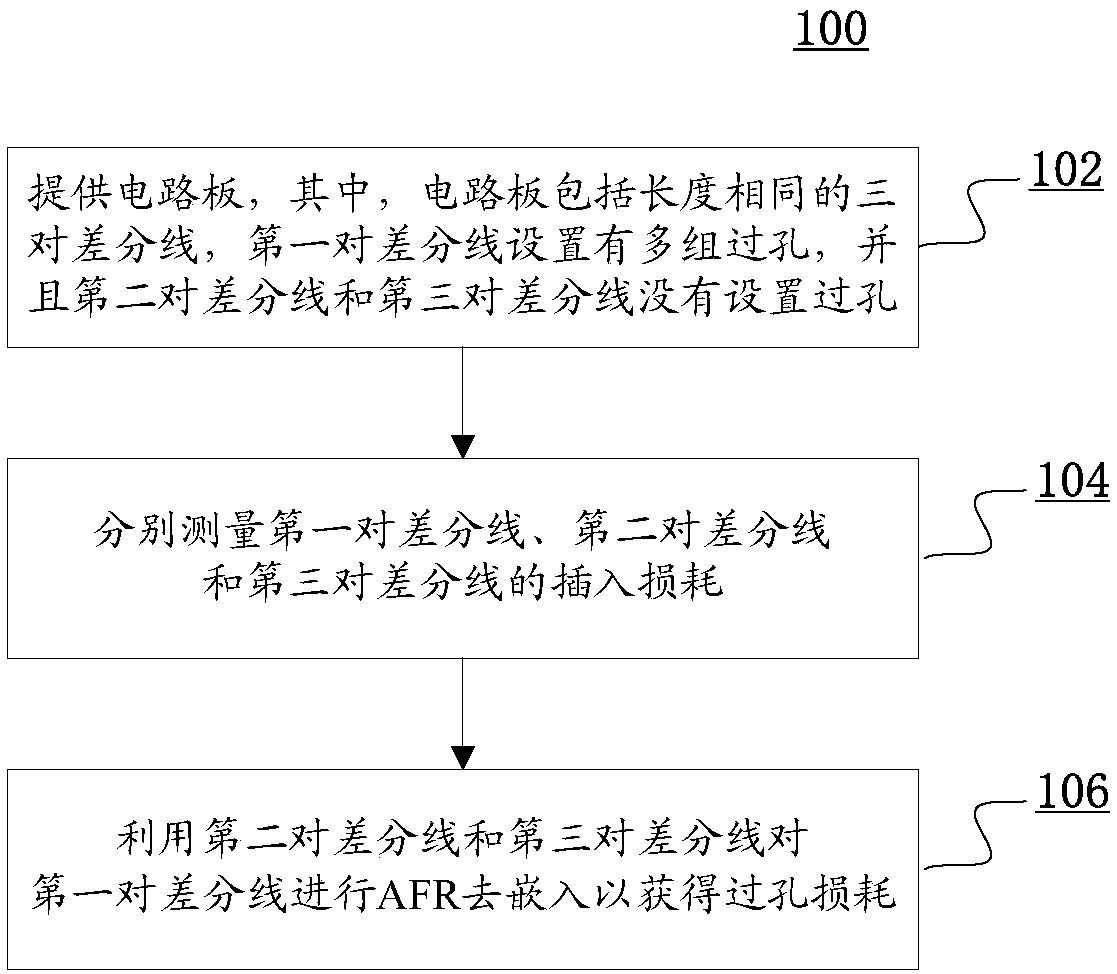
[0029] figure 1 is a flowchart of a method for testing via loss according to an embodiment of the present application. reference below figure 1 A method for testing via loss is described.

[0030] refer to figure 1 , according to an embodiment of the present application, the method 100 for testing via loss includes: step 102, providing a circuit board, wh...


PUM


Abstract

The invention provides a method and system for testing through-hole loss. The invention provides a method and a system for testing the through-hole loss. The method for testing the through-hole loss comprises the steps of providing a circuit board, wherein the circuit board comprises three pairs of differential lines with the same length, and a plurality of sets of through holes are formed in thefirst pair of differential lines, and the second pair of differential lines and the third pair of differential lines are not provided with through holes; respectively measuring the insertion losses ofthe first pair of differential lines, the second pair of differential lines and the third pair of differential lines; and performing AFR de-embedding on the first pair of differential lines by usingthe second pair of differential lines and the third pair of differential lines to obtain the through-hole loss. According to the invention, the influence of the PCB glass fiber effect and the processerror is reduced to a great extent, so that the loss of the measured differential through hole is more accurate.

Description

technical field [0001] The present application generally relates to the fields of electronic technology and performance measurement, and more particularly, to a method and system for testing via loss. Background technique [0002] With the high-speed development of various differential interconnection signal rates on the server Printed Circuit Board (PCB) board, and the limitation of total link loss by various protocols, the requirements for signal integrity are becoming increasingly stringent. For the complete link on the PCB wiring (also known as wiring) of the server, there are many factors that affect the signal integrity. Only by optimizing each discontinuous structure can a margin be left, so as to design a cost-effective and A link that meets the requirements of the protocol specification. Since there are connectors, inter-chip interconnections, space constraints, etc. in the wiring on the board, it is inevitable to introduce a signal layer change design, but the via...

Claims


Application Information

Patent Timeline
Patent Type & Authority Applications(China)
IPC IPC(8): G01R27/26
CPCG01R27/2694
Inventor 张颖赵振伟陈进
Owner 中科曙光信息产业成都有限公司
Why Eureka
Try Eureka