Method for fitting material loss angle

A technology for fitting materials and loss angles, which is applied in the field of electronics, can solve the problems of such parameter changes, and achieve the effects of small error, strong practicability, and easy promotion

Inactive Publication Date: 2014-08-06
LANGCHAO ELECTRONIC INFORMATION IND CO LTD
View PDF2 Cites 1 Cited by
  • Summary
  • Abstract
  • Description
  • Claims
  • Application Information

AI Technical Summary

Problems solved by technology

The dielectric constant and loss angle obtained by the manufacturer are generally for the individual material itself, but with the pressing of the PCB board and the mixed use of different types of materials, this parameter has changed

Method used


Image

  • Method for fitting material loss angle

Examples


Embodiment Construction

[0013] A method for fitting the material loss angle of the present invention will be described in detail below in conjunction with the accompanying drawings.

[0014] The specific implementation process of this method for fitting material loss angle is as follows:

[0015] First, a small test board needs to be added to the designed single board.

[0016] Then test the test board to get the impedance diagram and loss diagram and the results.

[0017] Then physically slice the test board to obtain real board layer information.

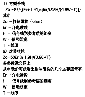
[0018] The dielectric constant of the material is calculated by the formula, the calculation formula is as attached figure 1 shown.

[0019] The loss angle is obtained by the simulation method, the transmission line model is established using the data of the physical slice, and the loss angle of the test is fitted, and the simulation data and the test data are fitted by continuously changing the loss angle until they are completely consistent, and the...


PUM


Abstract

The invention provides a method for fitting a material loss angle. The method comprises the steps of adding a small test board on a designed singe board; performing test on the test board to obtain an impedance graph, a loss graph and a result; performing physical slicing on the test board to obtain true board layer information; performing computing through a formula to obtain a permittivity of a material; obtaining the loss angle through a simulation method, establishing a transmission line model by means of data of the physical slicing, fitting transmission line model with the tested loss, and fitting simulated data with the tested data by changing the loss angles continuously until the simulated data and the tested data are consistent completely, wherein the obtained loss angle is the loss angle of the corresponding material. Compared with the prior art, the accurate permittivity and the accurate loss angle can be obtained, the obtained value is accurate and small in error, and strong practicability is achieved.

Description

technical field [0001] The invention relates to the field of electronic technology, in particular to a method for fitting material loss angles in the PCB board design process. Background technique [0002] In the modern high-speed digital world, signal integrity simulation is essential. The accuracy of simulation and the accuracy of model establishment are inseparable. How to accurately establish a simulation model, the dielectric constant of the material used and the accuracy of the loss angle are very necessary. The dielectric constant and loss angle obtained by the manufacturer are generally for the individual material itself, but with the pressing of the PCB board and the mixed use of different types of materials, this parameter has changed. So how can we get accurate dielectric constant and loss angle? Based on this, we now provide a method that can obtain accurate common sense and loss angle. Contents of the invention [0003] The technical task of the present in...

Claims


Application Information

Patent Timeline
Patent Type & Authority Applications(China)
IPC IPC(8): G06F17/50
Inventor 宗艳艳张柯柯
Owner LANGCHAO ELECTRONIC INFORMATION IND CO LTD
Why Eureka
Try Eureka