Autofocus camera lens
A camera lens and auto-focus technology, applied to focusing devices, instruments, installations, etc., can solve the problems of low pixels, increased lens volume and weight, and fixed, etc., to achieve the effect of a wide focus range
- Summary
- Abstract
- Description
- Claims
- Application Information
AI Technical Summary
Problems solved by technology
Method used
Image
Examples
Embodiment 1
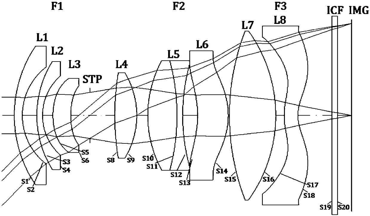
[0025] Such as figure 1 As shown, this embodiment includes: a first lens group F1 with negative power, a stop STP, a second lens group F2 with positive power; and a focus lens F3 with negative power.
[0026] The first lens group F1 includes: first to third lenses L1, L2, L3, wherein: L3 is a glass aspherical lens.
[0027] The second lens group F2 includes: fourth to seventh lenses L4, L5, L6 and L7, wherein: L5 is a cemented lens, and L6 is a glass aspheric lens.
[0028] The focusing lens F3 is a plastic aspheric lens L8.
[0029]
[0030]
[0031] The ones marked with "*" in the table are aspherical lenses.
[0032] In this embodiment, the third lens L3, the sixth lens L6 and the eighth lens L8 are aspheric lenses, and the formulas of their aspheric lens coefficients are as follows:
[0033] Among them: Z is the sag value of the lens, c is the reciprocal of the radius of curvature, h is the height from the lens edge to the optical axis, k is the conic coefficien...
Embodiment 2
[0041] The lens parameters of this embodiment are shown in the table below:
[0042]
[0043]
[0044] The aspheric coefficients of the present embodiment are listed in the following table:
[0045] S5 S6 S13 S14 S17 S18 K 1.8027 6.1312 -0.1532 -0.1781 -6.5300 -3.7722 A 0.0007 0.0008 0.0004 0.0002 -0.0047 -0.0036 B -4.71E-06 0.0002 3.91E-05 5.01E-05 0.0001 9.70E-05 C 4.35E-06 -5.68E-05 1.35E-06 -3.22E-07 -3.98E-08 -1.20E-06 D -8.37E-07 7.78E-06 -4.02E-08 3.86E-08 -3.34E-08 3.47E-10 E 8.35E-08 -2.03E-07 -2.17E-09 -5.33E-10 -6.02E-11 1.26E-10
[0046] Parameter table under different object distances:
[0047] endless 1m 0.3m focal length F 8.35 8.3 8.25 Fno 2.61 2.6 2.59 D1 endless 1000 300 D2 0.57 0.71 1.06 D3 3.24 3.1 2.75 FOV 90.1 90.3 90.5
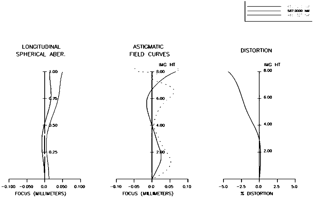
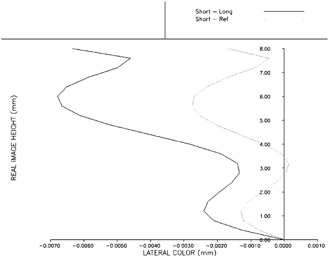
[0048] Such as Figure 4 Shown are the aberration diagrams of Example 2, including ax...
Embodiment 3
[0050] The difference between this embodiment and Embodiment 1 lies in that the angle of view of this embodiment is larger, the aperture is larger, and the third lens L3 and the sixth lens L6 use plastic aspheric lenses.
[0051] This embodiment includes: a first lens group F1 with negative power, a stop STP, a second lens group F2 with positive power; and a focus lens F3 with negative power.
[0052] The first lens group F1 includes: first to third lenses L1, L2, L3, wherein: L3 is a plastic aspheric lens.
[0053] The second lens group F2 includes: fourth to seventh lenses L4, L5, L6 and L7, wherein: L5 is a cemented lens, and L6 is a plastic aspheric lens.
[0054] The focusing lens F3 is a plastic aspheric lens L8.
[0055] R D Nd Vd OBJ D1 1 11.09 0.78 1.49 70.5 2 5.41 1.91 3 9.7 0.92 1.549 61.2 4 4.65 0.94 5 7.3 1.04 1.64 23 6 5.9 3.15 STP 0.28 8 30.3 2.21 1.549 68.2 ...
PUM
 Abstract
Description
Claims
Application Information
 - R&D
- Intellectual Property
- Life Sciences
- Materials
- Tech Scout
- Unparalleled Data Quality
- Higher Quality Content
- 60% Fewer Hallucinations
Browse by: Latest US Patents, China's latest patents, Technical Efficacy Thesaurus, Application Domain, Technology Topic, Popular Technical Reports.
© 2025 PatSnap. All rights reserved.Legal|Privacy policy|Modern Slavery Act Transparency Statement|Sitemap|About US| Contact US: help@patsnap.com


