Optical lens

An optical lens, lens technology

Active Publication Date: 2019-11-05
NINGBO SUNNY AUTOMOTIVE OPTECH
View PDF7 Cites 6 Cited by
  • Summary
  • Abstract
  • Description
  • Claims
  • Application Information

AI Technical Summary

Problems solved by technology

[0004] However, due to the large field of view, the focus range (DOF) of such optical lenses is generally small, and the focal length is generally short
This makes it unable to meet the requirements of better resolution performance, wider focus range and larger angular resolution at the same time

Method used


Image

  • Optical lens
  • Optical lens
  • Optical lens

Examples


Embodiment 1

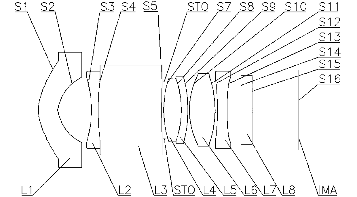
[0064] The following reference figure 1 The optical lens according to Embodiment 1 of the present application is described. figure 1 A schematic structural diagram of an optical lens according to Embodiment 1 of the present application is shown.

[0065] Such as figure 1 As shown, the optical lens includes a first lens L1, a second lens L2, a third lens L3, a fourth lens L4, a fifth lens L5, a sixth lens L6, and a seventh lens in order from the object side to the imaging side along the optical axis. Lens L7.

[0066] The first lens L1 is a meniscus lens with a convex surface facing the object side with negative refractive power. The object side surface S1 is a convex surface, and the image side surface S2 is a concave surface. The second lens L2 is a biconcave lens with negative refractive power, and the object side surface S3 and the image side surface S4 are both concave. The third lens L3 is a meniscus lens with positive refractive power, the object side surface S4 is a convex ...

Embodiment 2

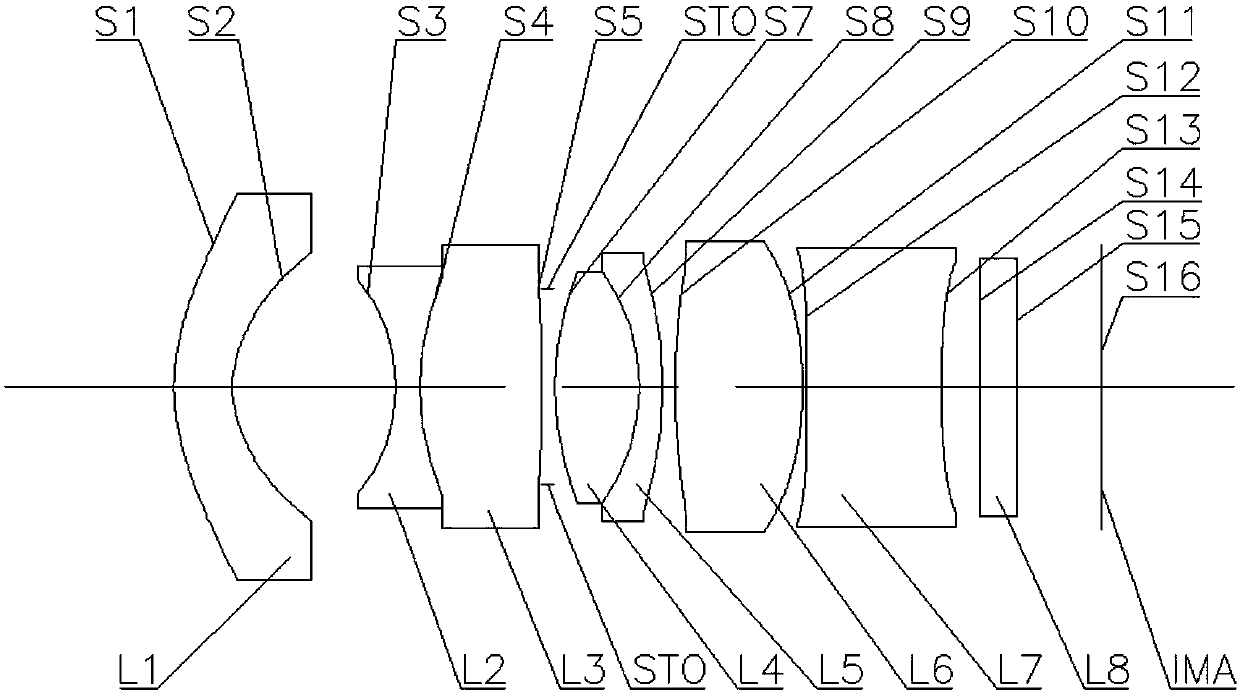
[0084] The following reference figure 2 The optical lens according to Embodiment 2 of the present application is described. figure 2 A schematic structural diagram of an optical lens according to Embodiment 2 of the present application is shown.

[0085] Such as figure 2 As shown, the optical lens includes a first lens L1, a second lens L2, a third lens L3, a fourth lens L4, a fifth lens L5, a sixth lens L6, and a seventh lens in order from the object side to the imaging side along the optical axis. Lens L7.

[0086] The first lens L1 is a meniscus lens with a convex surface facing the object side with negative refractive power. The object side surface S1 is a convex surface, and the image side surface S2 is a concave surface. The second lens L2 is a biconcave lens with negative refractive power, and the object side surface S3 and the image side surface S4 are both concave. The third lens L3 is a double convex lens with positive refractive power, and the object side surface S4 ...


PUM


Abstract

The invention discloses an optical lens. In one embodiment, the optical lens sequentially comprises a first lens, a second lens, a third lens, a fourth lens, a fifth lens, a sixth lens and a seventh lens from an object side to an image side along an optical axis, wherein the first lens has negative power and is in a crescent shape with a convex surface facing the object side, at least two adjacentof the second lens, the third lens, the fourth lens and the fifth lens are glued, the sixth lens has positive power, an object side surface and an image side surface of the sixth lens both are convexsurfaces, and the seventh lens has negative power. By the optical lens, wide focusing range, long-focus large visual-field angle, large central angle resolution and relatively high resolving power can be achieved.

Description

Technical field [0001] This application relates to the field of optics, specifically to optical lenses, and more specifically to optical lenses including seven lenses. Background technique [0002] In recent years, with the development of active safety in the automotive industry, the requirements for automotive front-view lenses have continued to increase. [0003] Large field of view, miniaturization, and high pixels are the prerequisites for this type of lens. At the same time, the requirements for the recognition of environmental objects are getting higher and higher. Specifically, the optical system is required to have a larger angular resolution. The angular resolution of the lens reflects the ability of the optical system to distinguish the smallest distance between two adjacent objects. [0004] However, due to the large field of view, the focus range (DOF) of this type of optical lens is generally small, and the focal length is generally short. This makes it unable to meet...

Claims


Application Information

Patent Timeline
Patent Type & Authority Applications(China)
IPC IPC(8): G02B13/00G02B13/06
CPCG02B13/0045G02B13/06
Inventor 谢前森李慧敏姚波周宝
Owner NINGBO SUNNY AUTOMOTIVE OPTECH
Why Eureka
Try Eureka