Eureka AIR delivers breakthrough ideas for toughest innovation challenges, trusted by R&D personnel around the world.

A low-grating-lobe multi-beam scanning method and system based on a spatial light modulator

A technology of spatial light modulator and scanning method, which is applied in the field of optical scanning, can solve the problems of pixel size grating lobe phenomenon, the inconvenience of phased array multi-beam technology, etc., and achieve the effect of reducing energy

Inactive Publication Date: 2020-01-31
BEIHANG UNIV
View PDF5 Cites 0 Cited by
  • Summary
  • Abstract
  • Description
  • Claims
  • Application Information

AI Technical Summary

Problems solved by technology

However, at present, due to the large pixel size of the liquid crystal spatial light modulator, serious grating lobes will be generated when multiple beams are deflected, which has caused great inconvenience to the phased array multi-beam technology.

Method used


Image

  • A low-grating-lobe multi-beam scanning method and system based on a spatial light modulator
  • A low-grating-lobe multi-beam scanning method and system based on a spatial light modulator
  • A low-grating-lobe multi-beam scanning method and system based on a spatial light modulator

Examples


specific Embodiment approach 1

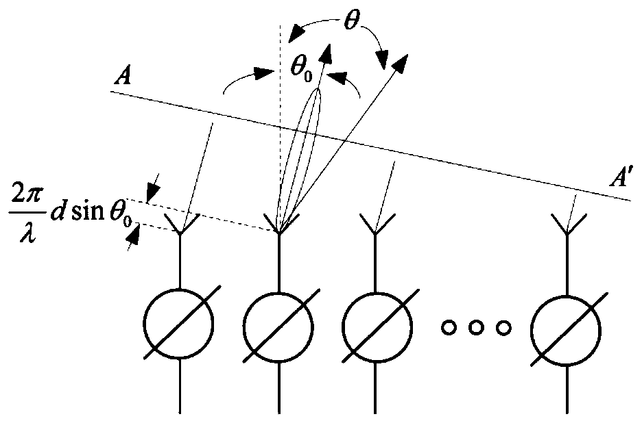
[0028] Specific implementation mode one: combine Figure 1 to Figure 6 This embodiment will be described. The liquid crystal spatial light modulator-based phased array low-lobe multi-beam scanning system described in this embodiment has two implementation forms, and the spatial light modulator may be a reflective spatial light modulator or a transmissive spatial light modulator.

[0029] When it is a reflective spatial light modulator, such as Figure 4 As shown, the system settings are as follows:

[0030] Laser instrument (1), polarizer (2), beam splitting prism (3), liquid crystal spatial light modulator (4-1), polarizer (5), lens (6) and CCD (7); laser instrument (1) The emitted parallel light beams are incident on the liquid crystal spatial light modulator (4-1) through the polarizer (2) and the dichroic prism (3), and the phase modulation of the liquid crystal spatial light modulator (4-1) produces multi-beams, which are incident on the light splitter The prism (3), a...

specific Embodiment approach 2

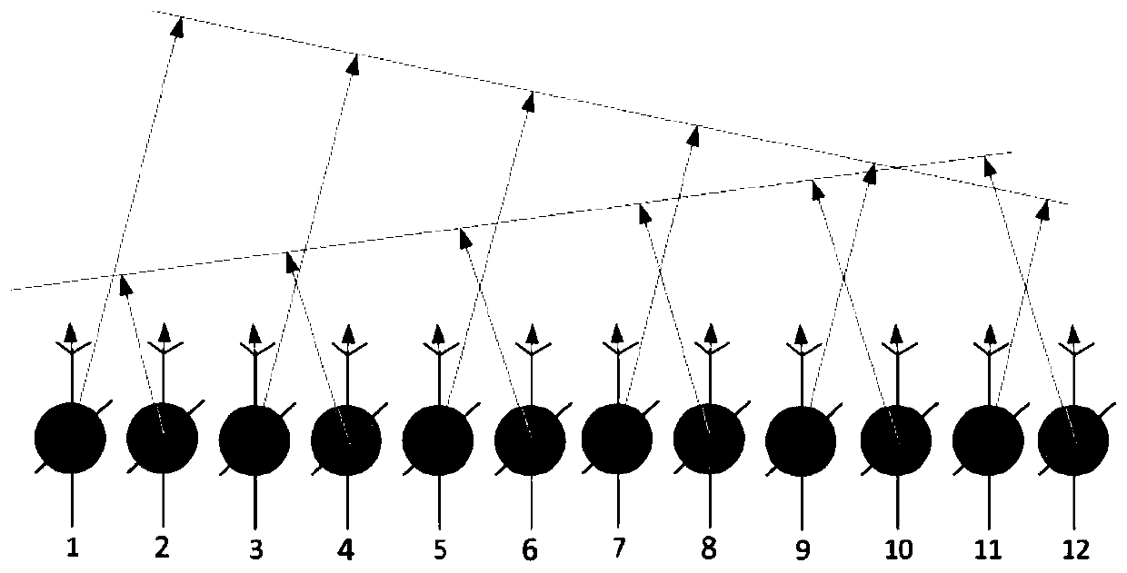
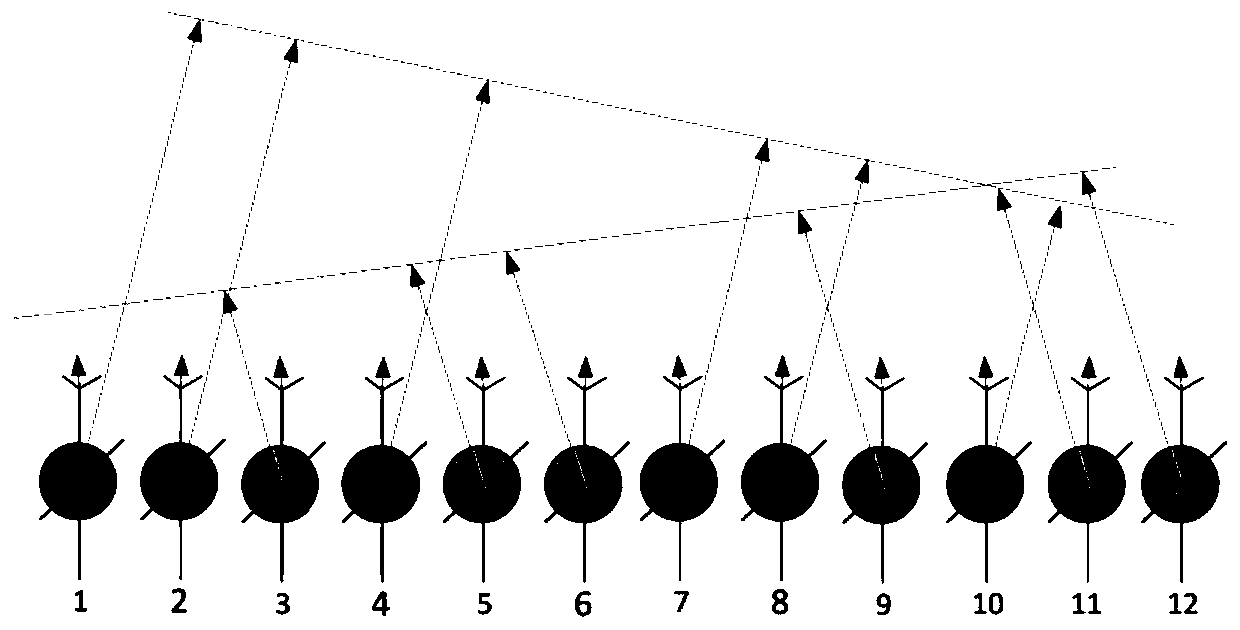
[0046] Embodiment 2: In Embodiment 1, it is demonstrated that two sets of beams with low grating lobes are generated by using a pixel group formed by selecting non-uniformly distributed pixel points. This method is still valid when more than two sets of beams need to be generated.

[0047] That is, when it is necessary to generate n groups of beams synchronously, it needs to contain n(n+1) pixels in one cycle; the first one contains n+1 pixels, 2 pixels point to the first beam, and the remaining n- One pixel points to other n-1 beams; the second one contains n+1 pixels, 2 pixels point to the second beam, and the remaining n-1 pixels point to other n-1 beams respectively ; By analogy, the nth one contains n+1 pixels, 2 pixels point to the nth beam, and the remaining n-1 pixels point to other n-1 beams respectively.

[0048] After the grouping is completed, the pixel differences between the rows and columns of the pixels in each group of beams are set in the manner described in...


PUM


Abstract

The invention discloses a low-grating-lobe multi-beam scanning method and system based on a spatial light modulator, and relates to the field of optical scanning, in particular to optical phase controlled matrix multi-beam scanning. According to the system, light beams are subjected to phase modulation of the spatial light modulator and then focused through a lens, multiple focal points are generated, and the positions of focal points on a focal plane can be changed by controlling a phase array loaded by the spatial light modulator so as to achieve two-dimensional scanning. By means of periodicity non-uniform distribution pixel mode, the phase array loaded by the spatial light modulator is controlled, grating lobes generated when the pixel size of the spatial light modulator is excessivelylarge can be effectively lowered, and the optical utilization efficiency is improved.

Description

technical field [0001] The invention relates to the field of optical scanning, in particular to optical phased array multi-beam scanning. Background technique [0002] The traditional beam deflection technology is based on mechanical devices to achieve beam deflection by changing the direction of the optical axis. It has complex structure, low precision, and high energy consumption. It needs to overcome the influence of inertia during continuous deflection, and its performance is greatly restricted. In 1971, Meyer produced and proposed a new phase modulator, which can control the phase change of each modulation unit, thereby realizing continuous scanning of the beam. In theory, it can well solve the problems faced by traditional beam deflection technology. [0003] In recent years, the beam deflection technology based on liquid crystal spatial light modulator has developed very rapidly, and the multi-beam scanning method based on liquid crystal spatial light modulator has a...

Claims


Application Information

Patent Timeline
Patent Type & Authority Patents(China)
IPC IPC(8): G02F1/1335G02F1/139
CPCG02F1/133526G02F1/133528G02F1/139
Inventor 张蓓刘雨赵子琦闫鹏胡庆雷
Owner BEIHANG UNIV
Why Eureka
Eureka Blog
Learn More