
Electrified locomotive isolating switch

A technology of isolating switches and locomotives, which is applied in the field of high-voltage electrical switchgear, can solve the problems of isolating switches occupying a large volume, being greatly affected by the external environment, and inconvenient to use, and achieving the effects of reducing partial discharge, high safety, and improving safety

Pending Publication Date: 2018-06-15
BEIHAI GALAXY SWITCH DEVICES
View PDF6 Cites 6 Cited by
  • Summary
  • Abstract
  • Description
  • Claims
  • Application Information

AI Technical Summary

Problems solved by technology

[0003] The problem to be solved by the present invention is to provide an electrified locomotive isolating switch, which solves the problems that the existing isolating switch occupies a large volume, is heavy, is greatly affected by the external environment, and is inconvenient to use

Method used


Image

  • Electrified locomotive isolating switch
  • Electrified locomotive isolating switch
  • Electrified locomotive isolating switch

Examples


Embodiment 1

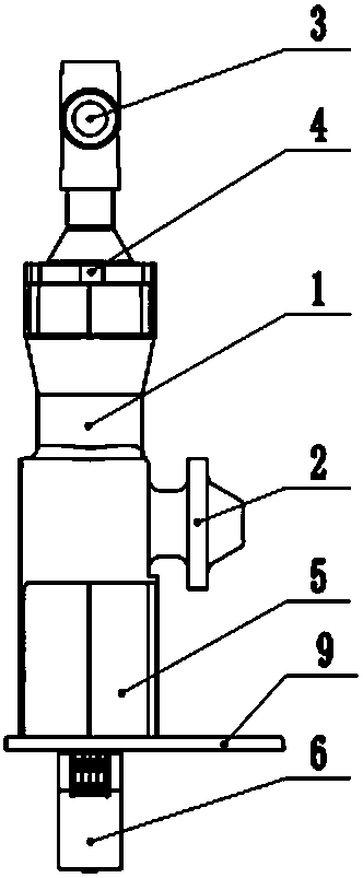
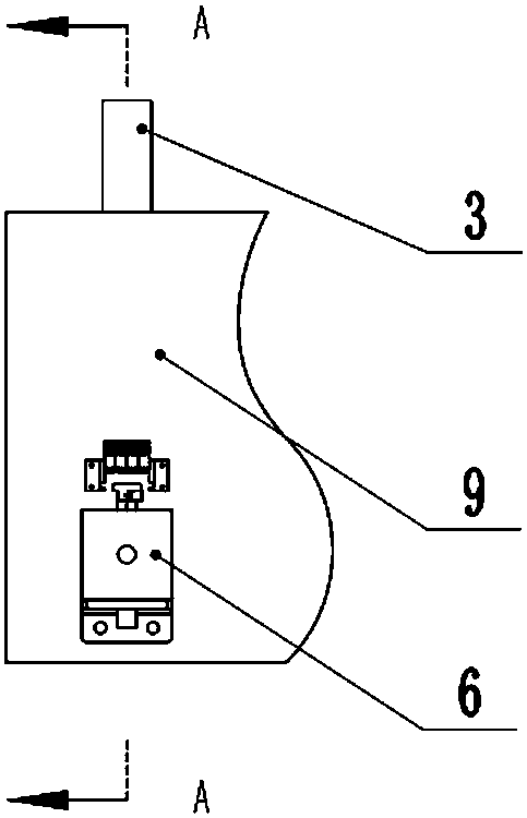
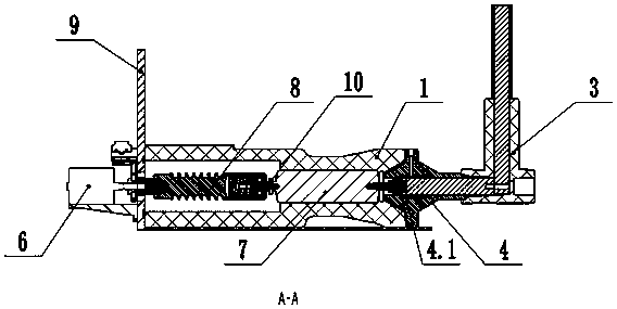
[0021] like figure 1 , figure 2 As shown, an electrified locomotive isolating switch, including isolating switch pole (1), bus connection plug (2), cable boot (3), bushing (4), permanent magnet operating mechanism (6), insulating pull rod ( 8) Mounting plate (9), which is characterized in that: the front part of the isolation switch pole (1) is a pull (5) rod chamber, and there is a vacuum interrupter (7) in the middle; the static end of the vacuum interrupter and the bushing ( 4) Connection, the moving end of the vacuum interrupter is connected to the insulating pull rod (8), and the moving end of the vacuum interrupter is connected to the bus connection plug (2) through a soft connection (10); the insulating pull rod (8) is located at the pole of the isolating switch Inside the rod chamber (5), pass through the mounting plate (9) and connect with the permanent magnet operating mechanism (6); the permanent magnet operating mechanism (6) is fixed in front of the mounting pla...

Embodiment 2

[0026] like Figure 4 , Figure 5 As shown, a spare isolating switch for an electrified locomotive includes isolating switch pole (1), busbar connecting plug (2), busbar connecting socket (11), grounding switch socket (12), cable boot (3), bushing ( 4), permanent magnet operating mechanism (6), insulating pull rod (8), and mounting plate (9), characterized in that: the front part of the isolation switch pole (1) is the pull (5) rod chamber, and the left side of the middle part is equipped with The bus connection socket (11), the bus connection plug (2) is provided on the right side, the earthing switch connection socket (12) is provided on the upper part, and the vacuum interrupter (7) is located in the middle; the static end of the vacuum interrupter and the bushing (4 ) connection, the moving end of the vacuum interrupter is connected with the insulating pull rod (8), and the moving end of the vacuum interrupter is connected with the circular busbar (1.3) through a conducti...


PUM


Abstract

The invention belongs to the field of high-voltage electrical switching equipment, and in particular relates to a high-voltage isolating switch for a railway locomotive. The high-voltage isolating switch comprises an isolating switch pole, a bus connection plug, a cable shoe, a sleeve, a permanent magnet actuator, an insulation pull rod and an installation plate; a vacuum arc extinguishing technology is adopted; a solid insulation technology is adopted in an insulation layer; an insulation material is made from epoxy resin or EPDM; a uniform ring is adopted at the internal joint; and a semi-conductive shielding technology is adopted on the external surface. The high-voltage isolating switch disclosed by the invention is standardized in interface, good in universality, easy to extend, smallin product volume and high in security.

Description

technical field [0001] The invention belongs to the field of high-voltage electrical switchgear, in particular to a high-voltage isolating switch for railway locomotives. Background technique [0002] With the continuous development of China's economy, railway transportation is playing an increasingly active role in the important means of transportation in China. In the future, China's railway construction will enter a golden period. With the arrival of the peak of railway construction, the market demand is increasingly strong. Conventional railway switchgear is gas-insulated metal-enclosed switchgear, which has problems such as large volume, risk of arcing, heavy weight, great influence from the external environment, and inconvenient use. Contents of the invention [0003] The problem to be solved by the present invention is to provide an electrified locomotive isolating switch, which solves the problems that the existing isolating switch occupies a large volume, is heav...

Claims


Application Information

Patent Timeline
Patent Type & Authority Applications(China)
IPC IPC(8): H01H33/66
CPCH01H33/66
Inventor 李章云曹玉生侯峰
Owner BEIHAI GALAXY SWITCH DEVICES
Learn More