An Overlapping Antenna Expansion Bracket

An antenna and fixing frame technology is applied in the field of antenna expansion and retraction support structures, which can solve the problems of not having the ability to fine-tune the omnidirectional freedom of the antenna reflection surface, and being unable to meet the requirements of antenna compaction site testing, so as to save development costs and be suitable for use in Wide range and good inheritance effect

Active Publication Date: 2019-12-20
CHINA ACADEMY OF SPACE TECHNOLOGY
View PDF9 Cites 0 Cited by
  • Summary
  • Abstract
  • Description
  • Claims
  • Application Information

AI Technical Summary

Problems solved by technology

[0004] In the existing technology, the traditional satellite antenna extension bracket does not have the ability to fine-tune the omnidirectional degree of freedom of the antenna reflection surface, and cannot meet the requirements of the antenna compact field test

Method used


Image

  • An Overlapping Antenna Expansion Bracket
  • An Overlapping Antenna Expansion Bracket
  • An Overlapping Antenna Expansion Bracket

Examples


Embodiment Construction

[0033] In order to make the solution of the present invention clearer, the present invention will be further described below in conjunction with the accompanying drawings and specific embodiments:

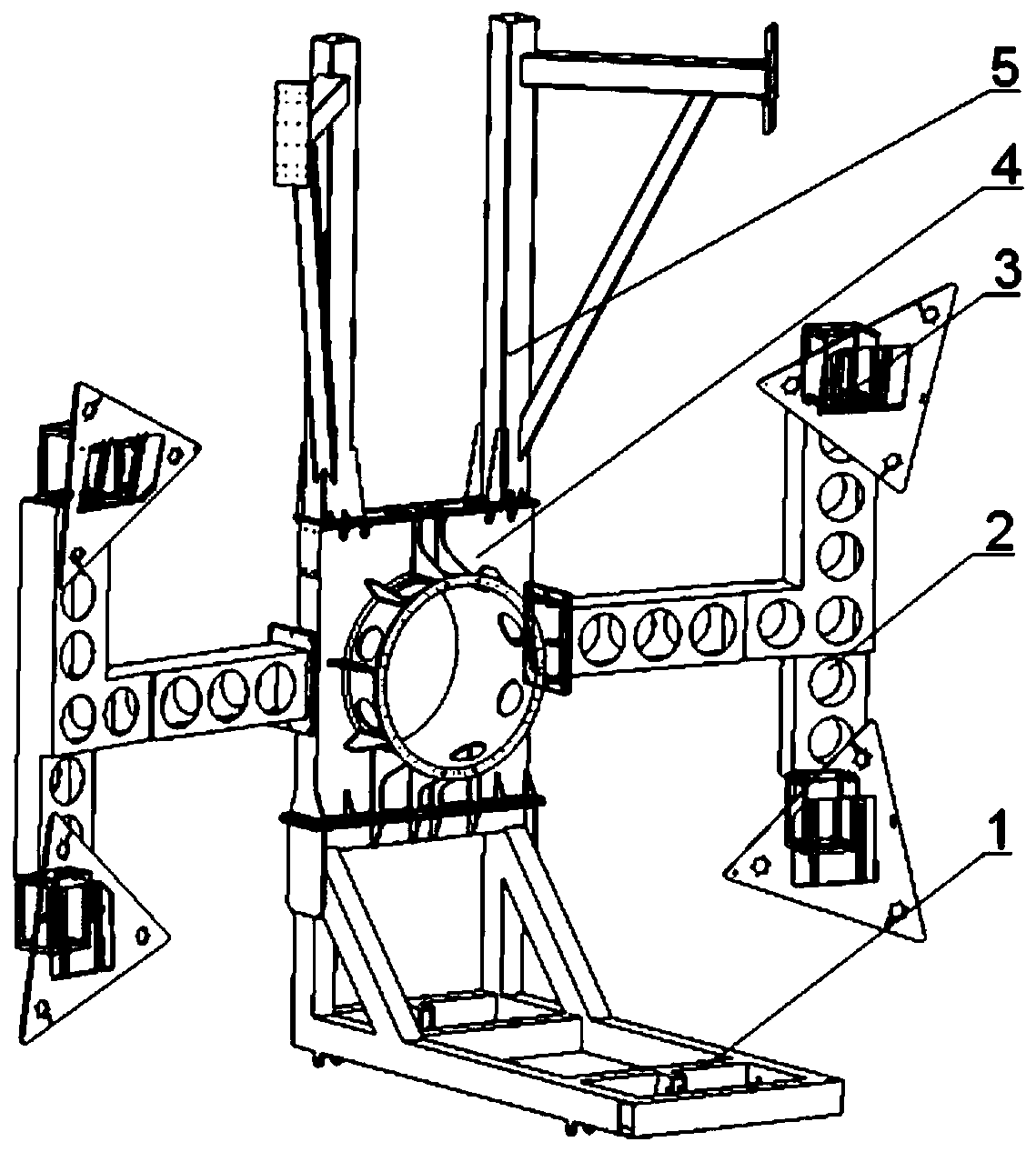
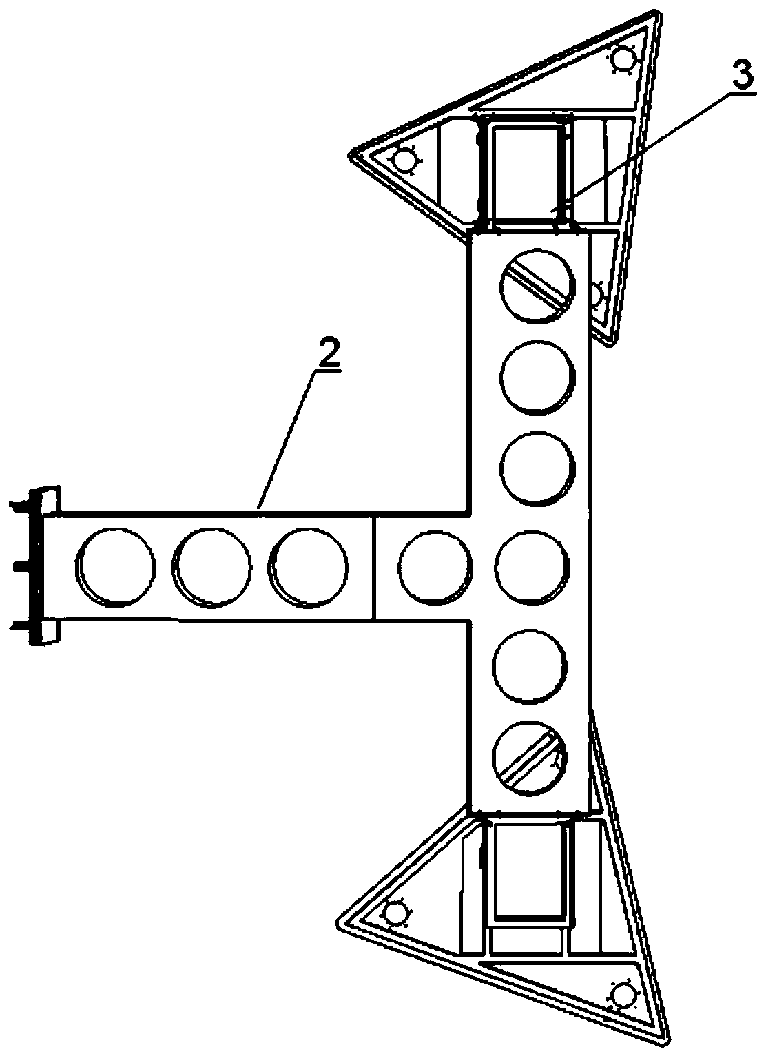
[0034] Such as Figure 1~2 As shown, a stackable antenna expansion bracket includes a body 1, a fixed frame 2, an adjuster 3, a flange 4 and a retractable frame 5; the flange 4 adopts a solid cubic structure, and two of the flanges 4 are symmetrical The sides of the flange are provided with a fixed frame 2 for installing the antenna, and the fixed frame 2 is equipped with an adjuster 3 for adjusting the omnidirectional degree of freedom of the antenna; the other two symmetrical sides of the flange 4 are respectively provided with a bracket for supporting the antenna. The main body 1 and the retractable frame 5 for hoisting the antenna and unloading the antenna reflector in zero gravity; the side of the flange plate 4 where the body 1, the fixed frame 2, and the retractable frame 5 ...


PUM


Abstract

The invention discloses an overlapping antenna unfolding support, which comprises a body, a fixing frame, a regulator, a flange plate and an unfolding frame, wherein the flange plate is of a solid cubic structure; the two symmetrical side surfaces of the flange plate are respectively provided with fixing frames used for installing the antenna; each of the fixed frames is provided with a regulatorused for regulating the omni-directional freedom degree of the antenna; the other two symmetrical side surfaces of the flange plate are respectively provided with the body used for supporting the antenna and the unfolding frame used for lifting the antenna and unloading an antenna reflector through zero gravity; the side face of the flange plate, which is not provided with the body, the fixing frame and the unfolding frame, is provided with a through hole used for assembling a satellite; and the edge of the through hole is provided with a flange used for containing the antenna. According to the unfolding support in the invention, the body, the fixing frame, the regulator, the flange plate and the unfolding frame are matched so that reliable fine adjustment of the omni-directional degree offreedom of the reflection surface of the antenna is realized, and the defects of a traditional satellite antenna unfolding support are overcome.

Description

technical field [0001] The invention relates to an overlapping antenna unfolding support, which is especially suitable for Ka frequency band user link antennas, and belongs to the technical field of antenna unfolding and retracting support structures. Background technique [0002] The satellite antenna subsystem includes Ka-band user link antennas (4 antennas in total), 1 Ka-band transmit and receive shared feeder link antenna, and 1 Ka-band beacon antenna, a total of 6 antennas; among them, the Ka-band user link antenna adopts 4-caliber multi-beam antenna technology, composed of 4 antennas: East Antenna South, East Antenna North, West Antenna South, and West Antenna North. [0003] According to the technical process of satellite prototype development, the antenna subsystem needs to be tested in a compact field state and payload test on the satellite platform. During the test period, the Ka user link antennas on the east and west boards of the satellite (a total of 4 deploy...

Claims


Application Information

Patent Timeline
Patent Type & Authority Patents(China)
IPC IPC(8): H01Q1/12H01Q1/08H01Q19/10
CPCH01Q1/1235H01Q19/10
Inventor 王江永许爱军靖法高秀会夏永泉
Owner CHINA ACADEMY OF SPACE TECHNOLOGY
Why Eureka
Try Eureka