System and method for lead fixation

a lead fixation and lead technology, applied in the field of medical stimulation systems, can solve the problems of scs system not being able to perform the intended function, scs system being less effective or even ineffective for its intended purpose, affecting treatment,

Inactive Publication Date: 2009-10-13
BOSTON SCI NEUROMODULATION CORP
View PDF28 Cites 33 Cited by
  • Summary
  • Abstract
  • Description
  • Claims
  • Application Information

AI Technical Summary

Benefits of technology

[0019]The lead designs with fixation sheath thus permits lead fixation to the dura of the spine in a manner that is flexible, non-migrational, and explantable. In addition, the lead designs permit focused stimulation energy and maximum contact between the electrode contacts and adjacent tissue and, moreover, can provide in certain embodiments, same-location implantation of new leads after explantation of old leads.

Problems solved by technology

Disadvantageously, when a neural stimulation lead chronically or temporarily moves, it can affect the treatment results.
For example, an SCS lead that moves up, down or rotates to the side of the spinal cord can result in therapy no longer being adequate to attain the desired paresthesia, thereby rendering the SCS system incapable of performing its intended function.
In some instances such adjustment of the stimulation energy may not be possible, thereby rendering the SCS system less effective or even ineffective for its intended purpose.
Thus, it is seen that maintaining the correct lead position is critical, and an undesirable movement of the lead can render the SCS, or other neural stimulation system, ineffective and useless.

Method used


Image

  • System and method for lead fixation
  • System and method for lead fixation
  • System and method for lead fixation

Examples


Embodiment Construction

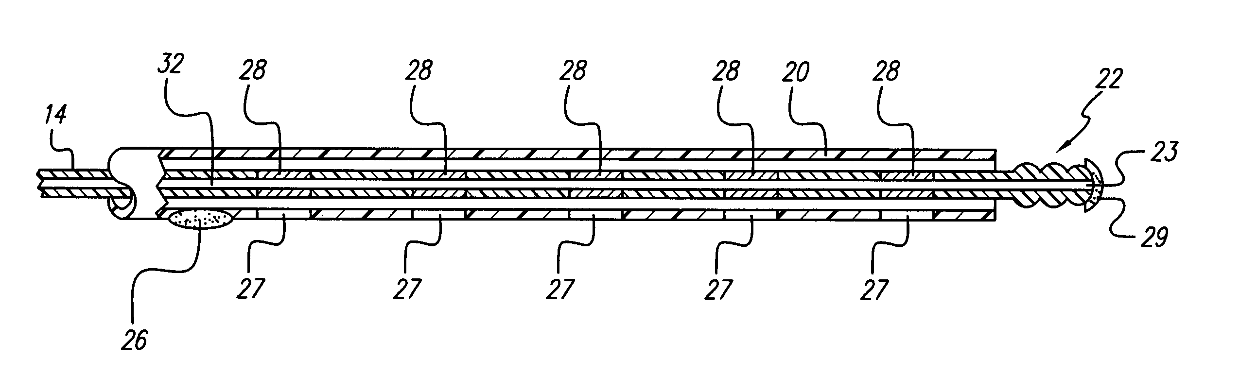
[0012]The present invention addresses the above and other needs by providing lead designs that permit improved fixation to the dura in a manner that also permits adequate flexibility to the lead to accommodate postural changes.

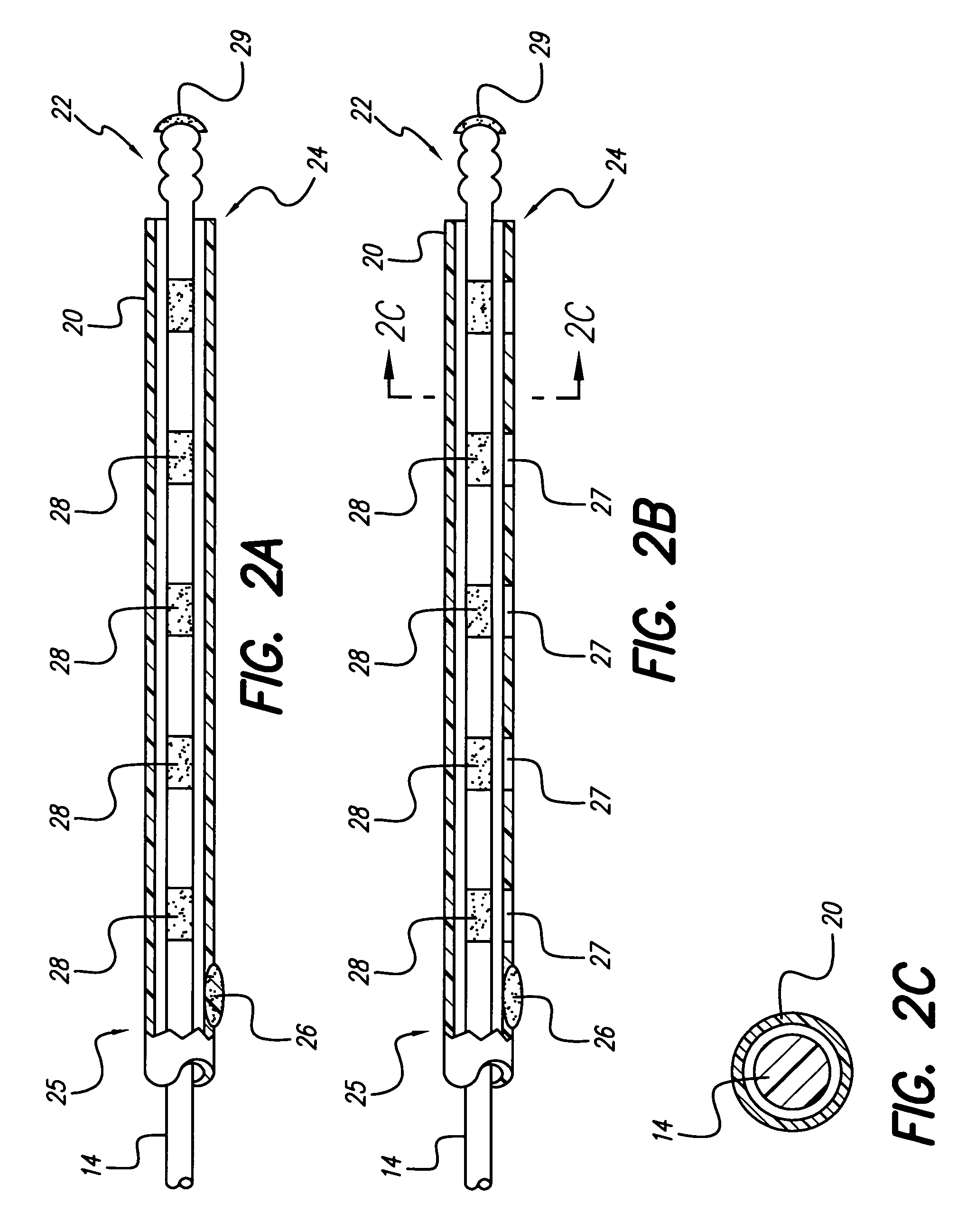
[0013]An electrode array of a lead is enclosed in a flexible tubing or sheath made of biocompatible material. The electrode array and sheath are inserted adjacent to the dura of the spine. The tip of the electrode array can be pitted, grooved or threaded in a manner that facilitates maturation of scar tissue over time near the electrode array tip. Scar maturation serves to fix the electrode array to the dura, thus minimizing lead migration. Nevertheless, the pitted, grooved, or threaded construction of the tip of the electrode array permits the lead to be easily explanted. A twisting action that applies rotational force or torque to the body of the lead during explantation can easily detach the grooved or threaded electrode array located at the distal tip of a...


PUM


Abstract

A medical lead includes a pitted, grooved or threaded electrode array tip and a flexible tube or sheath encompassing the electrode array located near the lead tip. In some embodiments, the electrode array adheres to tissue, the tube or sheath adheres to the electrode array at the distal end of the electrode array or the tube or sheath adheres to tissue at the proximal end of the tube or sheath. Embodiments of the tube or sheath may be made from biodegradable material and can include electrode windows spaced along the tube or sheath corresponding to placement of electrode contacts of the electrode array.

Description

[0001]The present application claims the benefit of U.S. Provisional Patent Application Ser. No. 60 / 503,518, filed 16 Sep. 2003, which application is herein incorporated by reference in its entirety.BACKGROUND OF THE INVENTION[0002]The present invention relates to medical stimulation systems, e.g., a spinal cord stimulation system. More particularly, the invention relates to medical stimulation leads that include lead fixation means, i.e., ways to ensure that the lead, once implanted, does not move away from its desired implant location.[0003]Spinal cord stimulation (SCS) is a well accepted clinical method for reducing pain in certain populations of patients. SCS systems typically include an implanted pulse generator, lead wires, and electrodes connected to the lead wires. The pulse generator generates electrical pulses that are delivered to the dorsal column fibers within the spinal cord through the electrodes which are implanted along the dura of the spinal cord. In a typical appl...

Claims


Application Information

Patent Timeline
Patent Type & Authority Patents(United States)
IPC IPC(8): A61N1/18
CPCA61N1/0551A61N1/0558
Inventor GRANDHE, SARVANI
Owner BOSTON SCI NEUROMODULATION CORP
Why Eureka
Try Eureka