A crane truss-type load-bearing beam

A load-bearing beam and truss-type technology, applied in the field of crane load-bearing beam structure, can solve the problems of increased construction difficulty, low safety factor, casualties, etc., and achieve the effect of low cost, less consumables, and large internal space

Active Publication Date: 2019-05-21
HARBIN INST OF TECH AT WEIHAI
View PDF7 Cites 0 Cited by
  • Summary
  • Abstract
  • Description
  • Claims
  • Application Information

AI Technical Summary

Problems solved by technology

The load-bearing beam of the crane with this structure has high strength and rigidity, but its mass is often too large, which will inevitably increase the difficulty of construction during production and installation, with many consumables and high cost
Between the transition of two plates, stress concentration often occurs due to sudden changes in the section, resulting in too low a local safety factor, so local failure and damage may occur, resulting in economic losses or even casualties

Method used


Image

  • A crane truss-type load-bearing beam
  • A crane truss-type load-bearing beam
  • A crane truss-type load-bearing beam

Examples


Embodiment Construction

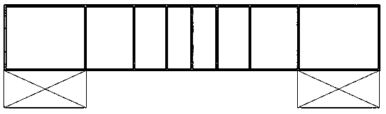
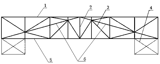
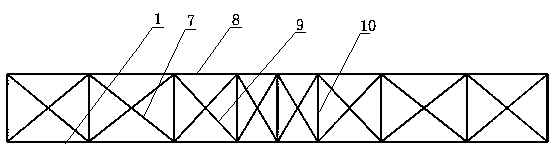
[0023] Such as Figure 1-3 The shown crane truss-type load-bearing beam is provided with two load-bearing beam supports 4 on the left and right, and the lower front beam bar and the lower rear beam bar 5 parallel to each other are fixed on the upper parts of the two load-bearing beam supports 4, and the lower front The upper front crossbeam 8 and the upper rear crossbeam 1 parallel to each other horizontally arranged above the crossbeam and the lower rear crossbeam 5; the lower front crossbeam, the lower rear crossbeam 5, the upper rear crossbeam 1 and the upper front Rod 8 forms a beam spanning the upper sides of the two load-bearing beam supports. The cross-section of the beam is rectangular. The lower front beam bar, the lower rear beam bar 5, the upper rear beam bar 1 and the upper front beam bar are distributed at the four corners of the rectangular section. . Between the lower front beam bar and the upper front beam bar, at least five front upper and lower support bars ...


PUM


Abstract

The invention provides a truss type bearing beam of a crane, and relates to bearing beam structures of the cranes. The truss type bearing beam of the crane is provided with a lower front cross beam rod, a lower rear cross beam rod, an upper front cross beam rod and a lower rear cross beam rod, wherein at least five upper and lower supporting rods are arranged below the lower front cross beam rod and the upper front cross beam, and at least five upper and lower supporting rods are arranged between the lower rear cross beam rod and the upper rear cross beam rod; the distance from a center part to the space between the upper and lower supporting rods at two ends gradually increases; a V-shaped inclined support is arranged between the center part of the upper front cross beam road and two endsof the lower front cross beam, and another V-shaped inclined support is arranged between the center part of the upper rear cross beam rod and two ends of the lower rear cross beam rod; an inclined beam supporting rod is arranged between the end part of each V-shaped inclined support and the adjacent cross beam rod; a front and rear connecting rod is arranged between the front cross beam rod and the rear cross beam rod. The truss type bearing beam of the crane has the advantages of being light in mass, convenient to produce and mount, low in material consumption, and low in cost.

Description

technical field [0001] The invention relates to a crane load-bearing beam structure, in detail, it is a crane truss-type load-bearing beam with small mass, convenient production and installation, less consumables, low cost and high safety factor. Background technique [0002] We know that bridge cranes are equipment placed in workshops, warehouses and stockyards to lift materials in the air, and are widely used in various engineering fields. For lifting devices with a very large load capacity such as bridge cranes used in mines, the load-bearing beams are mainly plate-type box structures, such as figure 1 As shown, the load-bearing beam of the plate box is welded by large steel plates to form the box surface, and a reinforced steel plate is placed horizontally on the inner section of the box surface; the load-bearing beam of the plate box is placed horizontally on two load-bearing beam supports to form a crane support. The load-bearing beam of the crane with this structure ...

Claims


Application Information

Patent Timeline
Patent Type & Authority Patents(China)
IPC IPC(8): B66C6/00
CPCB66C6/00
Inventor 王大方刘洋杨博涵蔡金逸徐泽绪汪井威汤志皓
Owner HARBIN INST OF TECH AT WEIHAI
Why Eureka
Try Eureka