Granary having directional ventilation function

A granary and functional technology, applied in the field of granary with directional ventilation function, can solve problems such as poor ventilation and grain rot, and achieve the effect of improving ventilation effect, avoiding air overflow, and improving the utilization rate of blasting.

Inactive Publication Date: 2018-06-22
河南创卓仓储科技股份有限公司
View PDF1 Cites 1 Cited by
  • Summary
  • Abstract
  • Description
  • Claims
  • Application Information

AI Technical Summary

Problems solved by technology

[0005] The invention overcomes the deficiencies of the prior art, provides a granary capable of directional ventilation for grain, and solves the problem of grain rot caused by poor ventilation in the existing granary

Method used


Image

  • Granary having directional ventilation function
  • Granary having directional ventilation function

Examples


Embodiment 1

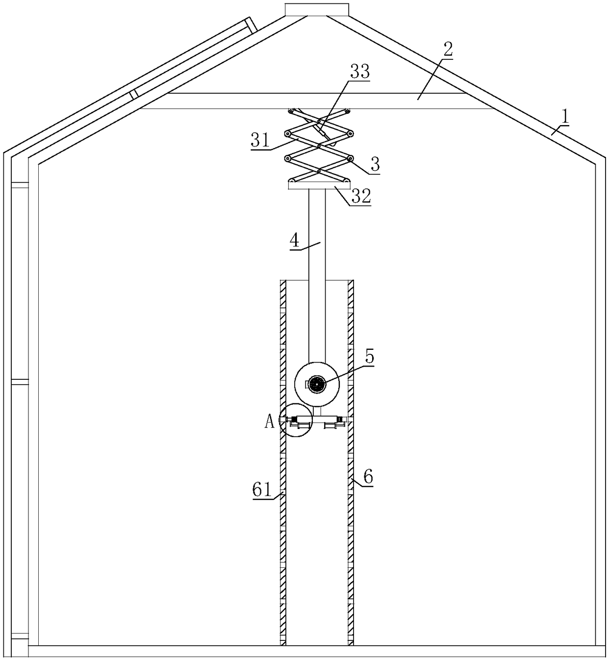
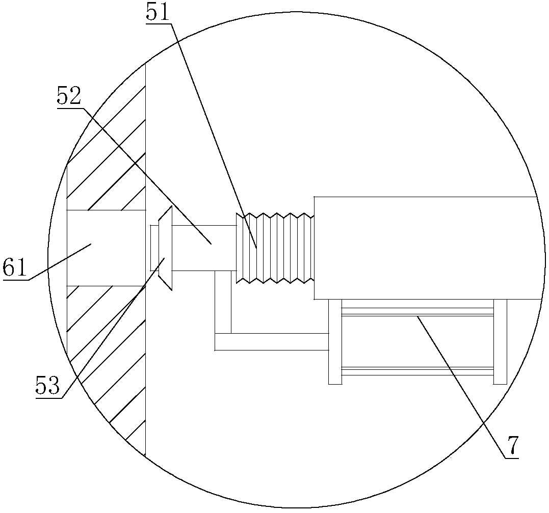
[0020] A granary with a directional ventilation function, comprising a granary main body 1; a horizontal plate 2 is connected to the top of the granary main body 1, a scissor-type lifting mechanism 3 is installed on the horizontal plate 2, and a lifting mechanism 3 is connected to the other end of the scissor-type lifting mechanism 3. Rod 4, the other end of elevating rod 4 is connected with air blower 5, and vent pipe 6 is installed in granary main body 1, and vent pipe 6 is provided with some ventilation holes 61, and air blower 5 and elevating rod 4 are sleeved in air pipe 6; The air outlet pipe of 5 is connected with corrugated hose 51, and the other end of corrugated hose 51 is connected with blower head 52 for connecting ventilation hole 61, and the air outlet pipe of blower 5 is connected with cylinder 7, and the piston rod of cylinder 7 is connected with the blower. Limelight 52 connection.

[0021] The scissor lifting mechanism 3 of the present invention can drive the...

Embodiment 2

[0023] On the basis of Embodiment 1, the scissor lift mechanism 3 includes a scissor lift frame 31, one end of the scissor lift frame 31 is hinged to the horizontal plate 2, and the other end of the scissor lift frame 31 is hinged to a connection A lifting hydraulic cylinder 33 is hinged between the plate 32, the horizontal plate 2 and the scissor lift frame 31.

[0024] When lifting hydraulic cylinder 33 moves, scissor lift frame 31 stretches out or retracts accordingly, and elevating rod 4 can push blower 5 to the grain position that needs blowing, realizes accurate air supply.

Embodiment 3

[0026] On the basis of Embodiment 1 or Embodiment 2, a sealing plug 53 is connected to the blower head 52, and the shape of the sealing plug 53 is a truncated cone.

[0027] The sealing plug 53 can effectively seal the gap between the blower head 52 and the ventilation hole 61 , further increases the amount of air flow through the ventilation hole 61 , and improves the ventilation effect.


PUM


Abstract

The invention relates to the field of grain storage equipment, in particular to a granary having a directional ventilation function. The granary comprises a granary body, the top of the granary body is connected with a transverse plate, a scissor-fork lifting mechanism is mounted on the transverse plate, one end of the scissor-fork lifting mechanism is connected with a lifting rod while the otherend of the same is connected with an air blower, a ventilation pipe is mounted in the granary body, a plurality of ventilation holes are formed in the ventilation pipe, and the air blower and the lifting rod are arranged in the ventilation pipe in a sleeved manner; an air outgoing pipe of the air blower is connected with a corrugated hose, the other end of the corrugated hose is connected with anair blowing head for being connected with the ventilation holes, a cylinder is connected on the air outgoing pipe, and a piston rod of the cylinder is connected with the air blowing head. The granarycan directionally ventilate grain, and the problem of grain rotting caused by the fact that ventilation of existing granaries is obstructed is solved.

Description

technical field [0001] The invention relates to the field of grain storage equipment, in particular to a granary with directional ventilation function. Background technique [0002] A granary is a special building for storing grain. my country is a large agricultural country with a long history of grain production and storage. According to a large number of cultural relics and historical research unearthed in China in the past fifty years, China's primitive agriculture was enlightened in the late Paleolithic Age and developed in the new era. The storage of grain is the continuation of agricultural cultivation, and storage technology develops along with the development of agriculture. After entering the new era, with the development of primitive agriculture, agricultural production has formed a certain scale, and grain surplus has gradually developed from grain processing to storage. Classification of granary: 1. Classification according to the grain storage method in the w...

Claims


Application Information

Patent Timeline
Patent Type & Authority Applications(China)
IPC IPC(8): A01F25/14A01F25/22
CPCA01F25/14A01F25/22
Inventor 李凯
Owner 河南创卓仓储科技股份有限公司
Why Eureka
Try Eureka