Spiral type rope locking device

A rope lock, screw technology, applied in the direction of transmission element or pulley rope or cable, textile cable, belt/chain/gear, etc. To achieve the effect of simple structure, simplified operation steps, and improved force form

Pending Publication Date: 2018-06-22
丹阳昊天飞行器技术有限公司
View PDF7 Cites 1 Cited by
  • Summary
  • Abstract
  • Description
  • Claims
  • Application Information

AI Technical Summary

Problems solved by technology

For heavy-duty ropes, the size is relatively thick and the material is hard, so it is very difficult to tie a knot, and it is easy to loosen. If the knot is not firm, it will bring great safety hazards.

Method used


Image

  • Spiral type rope locking device
  • Spiral type rope locking device
  • Spiral type rope locking device

Examples


Embodiment 1

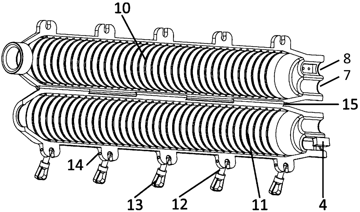
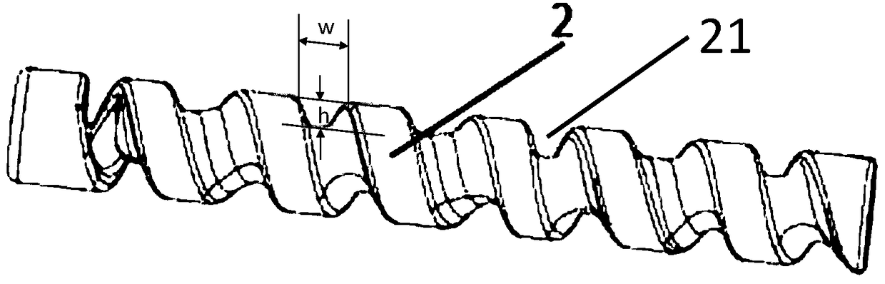
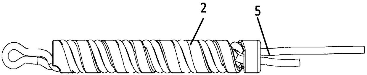
[0034] Such as Figure 1-Figure 5 As shown, Embodiment 1 of the present invention provides a screw-type rope lock, which includes a hinged hoop 1 , a screw column 2 , a support ring 3 , a rope inlet chamber 7 , a rope outlet chamber 8 and a pressing block 4 .

[0035] Such as figure 1 As shown, the upper cover 10 and the lower cover 11 of the hinged hoop 1 are cavity structures, which are connected and rotatable through the hinge shaft 15 , and form an internal cavity when closed to accommodate the screw column 2 . The cavity is narrowed at both ends of the hoop 1 , thereby forming two circular frustums at both ends of the hoop 1 for constraining the axial movement of the screw column 2 .

[0036] Inside the cavity, that is, on the inner surface of the hoop 1, annular grooves parallel to each other are processed to form anti-skid bosses at equal intervals.

[0037] One end of loam cake 10 (such as Figure 4 The right end) is provided with a support ring 3, the rope enters a...

Embodiment 2

[0047]In another simpler embodiment, the support ring 3, the rope access cavity, and the pressure block 4 can all be omitted. The cavity of the hoop 1 is narrowed at both ends of the hoop 1 , thereby accommodating the screw column 2 in the cavity, and cannot pass through the cavity freely. This embodiment is suitable for application environments with relatively small loads.


PUM


Abstract

The invention provides a spiral type rope locking device which is mainly composed of a hoop, a spiral pillar, an optional optical ring and an optional pressing block. A rope is used for spirally winding the rope on a threaded groove of the spiral pillar and is hooped through the hoop. The pressing block arranged at one end of the rope locking device is further adopted for knotting the rope. The spiral type rope locking device has the beneficial effects that operation is simple, safety and reliability are achieved, and the rope is not damaged.

Description

technical field [0001] The invention belongs to the field of machinery, and relates to a rope knotting device, in particular to a spiral rope lock. Background technique [0002] Rope is widely used in people's work and life as a common tool. At present, the connection and fixation of ropes are often realized by knotting, and traditional knotting methods are divided into two categories: slipknots and dead knots. Slip knots are easy to untie, but have the problem of being easy to loosen. Dead knots are firmly connected, but not easy to untie, and cannot be re-knotted for non-permanently fixed and connected ropes. At the same time, the traditional knotting method will cause the phenomenon of multi-strand ropes being entangled with each other at the knot. When the rope is stressed, the ropes at the knot will squeeze each other, reducing the ultimate load of the rope. Since the knot is the weakest link in the stress of the rope, long-term exposure will also accelerate the aging...

Claims


Application Information

Patent Timeline
Patent Type & Authority Applications(China)
IPC IPC(8): F16G11/00
CPCF16G11/00
Inventor 郑杨涛施志强
Owner 丹阳昊天飞行器技术有限公司
Why Eureka
Try Eureka