Supercharge Your Innovation With Domain-Expert AI Agents!

Continuously variable transmission device

A transmission device, continuously variable speed technology, applied in the direction of transmission device, friction transmission device, friction roller transmission device, etc., can solve the problems of pulley wear, poor shifting continuity, and shifting feeling of frustration.

Pending Publication Date: 2018-06-22
BEINENG TECH GUANGZHOU CO LTD
View PDF0 Cites 0 Cited by
  • Summary
  • Abstract
  • Description
  • Claims
  • Application Information

AI Technical Summary

Problems solved by technology

[0002] Most of the current transmissions are gear transmissions. This type of transmission is generally used with a clutch or a hydraulic torque converter. The structure is relatively complicated, the continuity of the shift is not good, and there is a sense of frustration when shifting gears.
The emerging belt-type continuously variable transmission can continuously change speed and torque, but its transmission belt, as the core mechanism of the belt-type continuously variable transmission, is a vulnerable part. The steel transmission belt is often prone to serious wear and tear with the steel pulley. And the transmission belt made of rubber is easy to age and crack

Method used


Image

  • Continuously variable transmission device
  • Continuously variable transmission device
  • Continuously variable transmission device

Examples


Embodiment Construction

[0017] The specific implementation manners of the present invention will be further described in detail below in conjunction with the accompanying drawings and embodiments. The following examples are used to illustrate the present invention, but are not intended to limit the scope of the present invention.

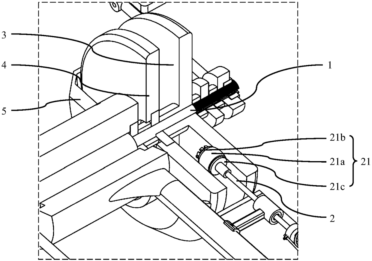
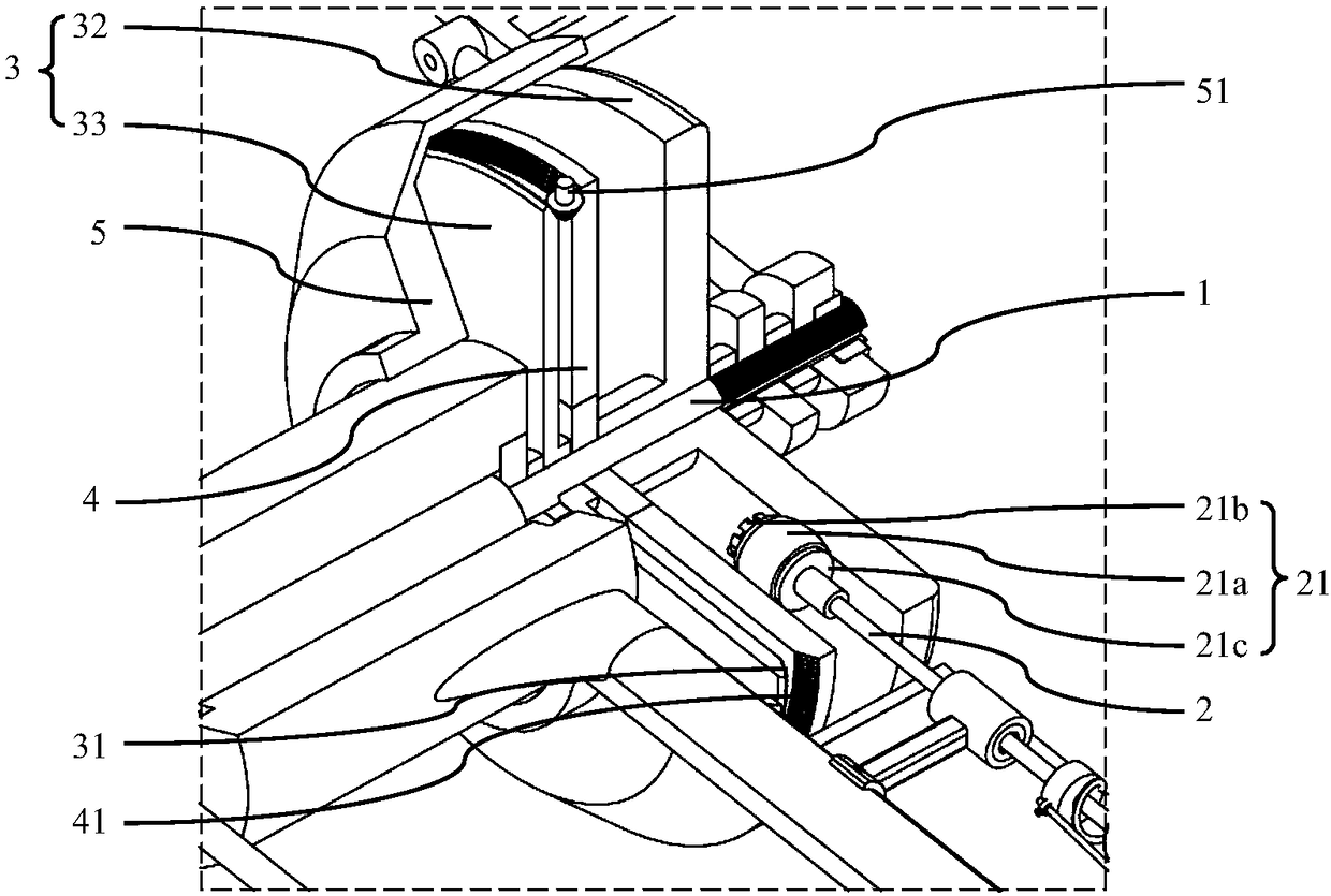
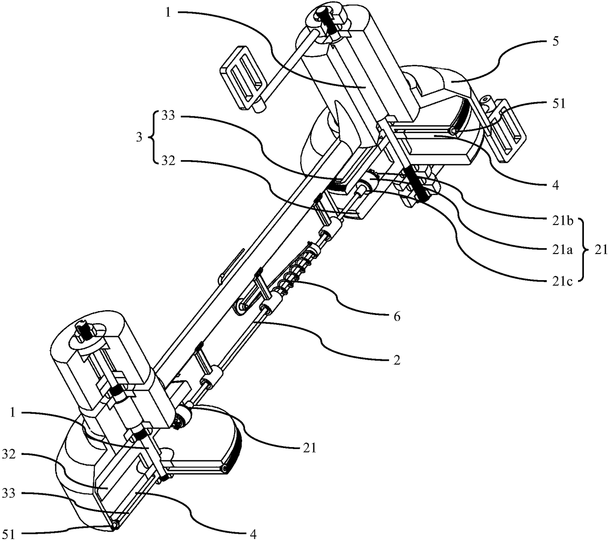
[0018] combine figure 1 As shown, the continuously variable transmission device of the present invention is schematically shown, including a first shaft 1, a second shaft 2 and a speed change mechanism. The rotary member 21 at the end of the second shaft 2, the driving disc 3 is fixedly sleeved on the first shaft 1, and the driven disc 4 is rotatably sleeved on the first shaft 1; the rotary member 21 is arranged on the driving disc 3 and the slave between the driving discs 4 , and the outer wall of the rotating member 21 abuts against the disc surface of the driving disc 3 and the disc surface of the driven disc 4 . When the first shaft 1 rotates, the driving disk 3 rota...


PUM


Abstract

The invention relates to the field of transmissions, and specifically relates to a continuously variable transmission device. The device comprises a first shaft, a second shaft and a speed variation mechanism, wherein the speed variation mechanism comprises a driving plate, a driven plate and a gyrating part; the driving plate and the driven plate are oppositely arranged; the gyrating part is coaxially connected to the end part of the second shaft; the driving plate fixedly sleeves the first shaft; the driven plate rotatably sleeves the first shaft; the gyrating part is arranged between the driving plate and the driven plate; the outer sidewall of the gyrating part is propped to the surfaces of the driving plate and the driven plate. According to the continuously variable transmission device, the speed ratio of the device can be changed based on the change of the distance between the gyrating part and an axis of the first shaft.

Description

technical field [0001] The invention relates to the field of transmissions, in particular to a continuously variable transmission device. Background technique [0002] Most of the current transmissions are gear transmissions. This type of transmission is generally used with a clutch or a torque converter. The structure is relatively complicated, the continuity of the shift is not good, and there is a sense of frustration when shifting. The emerging belt-type continuously variable transmission can continuously change speed and torque, but its transmission belt, as the core mechanism of the belt-type continuously variable transmission, is a vulnerable part. The steel transmission belt is often prone to serious wear and tear with the steel pulley. And the transmission belt made of rubber is easy to age and crack. Contents of the invention [0003] In order to solve the above problems, the object of the present invention is to provide a continuously variable transmission devi...

Claims


Application Information

Patent Timeline
IPC IPC(8): F16H15/04B62M13/02
CPCF16H15/04B62M13/02
Inventor 李钊河甄志立
Owner BEINENG TECH GUANGZHOU CO LTD
Features
  • R&D
  • Intellectual Property
  • Life Sciences
  • Materials
  • Tech Scout
  • Unparalleled Data Quality
  • Higher Quality Content
  • 60% Fewer Hallucinations
Learn More