Eureka AIR delivers breakthrough ideas for toughest innovation challenges, trusted by R&D personnel around the world.

Direct current power transmission system commutation failure fault recovery method

A DC transmission system, commutation failure technology, applied in information technology support systems, power transmission AC networks, etc., can solve the problems of increasing the off-angle DC current, unable to fundamentally avoid commutation failure, etc., to maintain stability , Fast DC power recovery, the effect of suppressing continuous commutation failure

Active Publication Date: 2018-06-22
STATE GRID QINGHAI ELECTRIC POWER +2
View PDF6 Cites 7 Cited by
  • Summary
  • Abstract
  • Description
  • Claims
  • Application Information

AI Technical Summary

Problems solved by technology

For the prediction and preventive control of commutation failure, scholars have proposed a variety of improved prediction algorithms, including methods to improve the detection speed and accuracy near the zero crossing point, and adopt adaptive fuzzy control or PI control to deal with different DC control modes and operating conditions. Influenced by conditions, most of them are increasing the turn-off angle or reducing the DC current, which can be used as an auxiliary preventive method for commutation failure, but it cannot fundamentally avoid the continuous occurrence of commutation failure

Method used


Image

  • Direct current power transmission system commutation failure fault recovery method
  • Direct current power transmission system commutation failure fault recovery method

Examples


Embodiment Construction

[0028] The technical solutions of the present invention will be described in further detail below in conjunction with the accompanying drawings and specific embodiments, so that those skilled in the art can better understand the present invention and implement it, but the embodiments are not intended to limit the present invention.

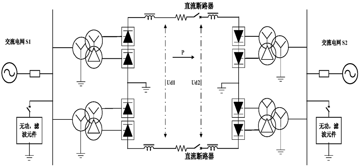
[0029] for figure 1 A bipolar DC transmission system is shown, including: a rectifier converter station and an inverter converter station, which are connected by two DC transmission lines, wherein: the rectifier converter station is used to convert the three-phase AC power of the sending end AC power grid After the DC power is transmitted to the inverter converter station through the DC transmission line, the inverter converter station is used to convert the DC power into three-phase AC power and then transmit it to the receiving-end AC power grid. Passive filters may or may not be connected to the incoming bus of the AC power grid at the sending ...


PUM


Abstract

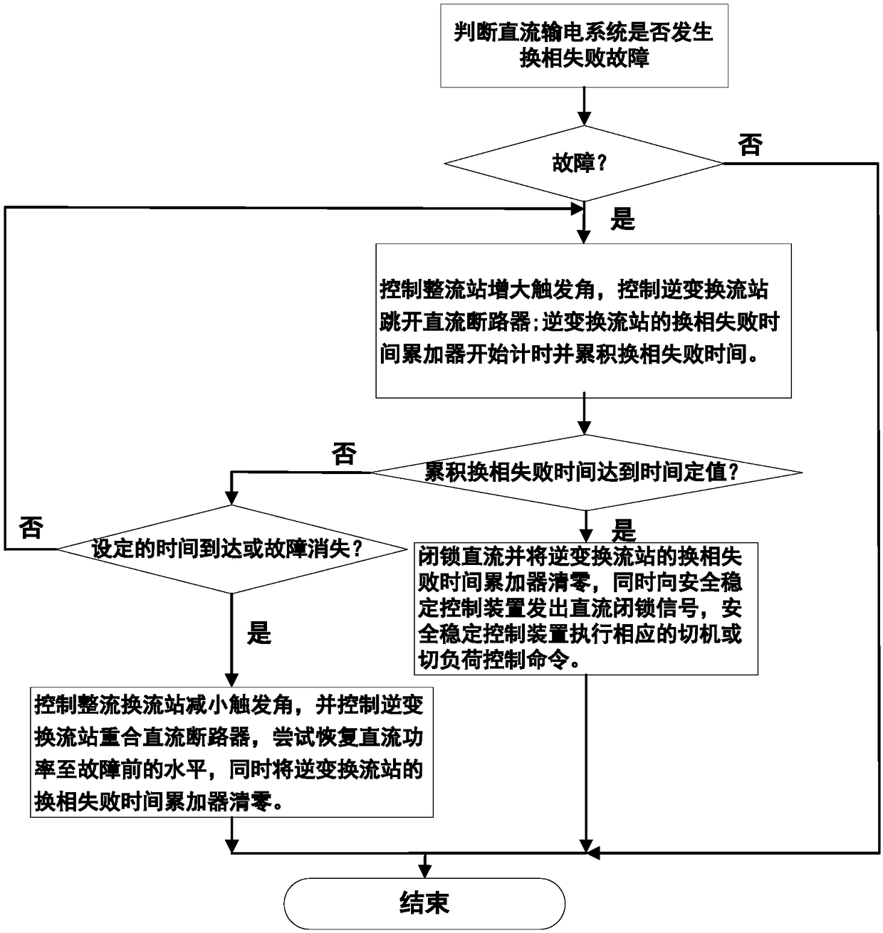
The invention discloses a direct current power transmission system commutation failure fault recovery method. The method comprises the following steps of step1, collecting the direct voltage and the direct current of a direct current power transmission system, and the alternating voltage of an alternating current power grid connected to a reverse converter station; step2, according to an analog quantity collected in step 1, determining whether the direct current power transmission system has a commutation failure fault; step3, If the commutation failure fault occurs, making a rectifier converter station increase a firing angle, and making the reverse converter station trip off a direct current circuit breaker, simultaneously using the commutation failure time accumulator of the reverse converter station to start carrying out timekeeping and accumulate commutation failure time; when waiting set time is up or the commutation failure fault disappears within a certain time, making the rectifier converter station reduce the firing angle, making the reverse converter station reconnect the direct current circuit breaker, trying to restore direct current power to a level before the fault and resetting the commutation failure time accumulator of the reverse converter station. In the invention, the commutation failure fault of the direct current power transmission system can be effectively processed, and a condition that a power fluctuation brought by a direct current continuous commutation failure jeopardizes the safety and stability of the connected alternating current power grid is avoided.

Description

technical field [0001] The invention belongs to the field of direct current power transmission, and particularly relates to a fault recovery method for a commutation failure of a direct current power transmission system. Background technique [0002] The thyristor-based grid commutation HVDC transmission system has large transmission capacity, low line cost, strong asynchronous networking capability, and has great advantages in long-distance large-capacity power transmission and large-area networking. The high-density connection of the DC transmission system to the AC power grid makes the interaction between the AC and DC systems increasingly complex, which brings huge challenges to the safe and stable operation of the power grid. The commutation failures of high-power DC systems are relatively common, and are mostly caused by the failure of the AC system at the receiving end. During the commutation failure, the DC power drops sharply, the synchronous generator of the DC se...

Claims


Application Information

Patent Timeline
IPC IPC(8): H02J3/36
CPCH02J3/36Y02E60/60Y04S10/52
Inventor 全生明祁太元李生张洪平弓建荣李海峰董凌张永祥张节潭方保民张桂红温广李红志刘庆彪宋锐孔祥鹏王轩赵世昌赵文强思晓兰侍乔明刘立敏王永平王宁霞梁建龙罗敏陈卉孟可风薛俊茹李春来丛贵斌杨嘉汪凤月刘可王少飞车克杉杨文丽赵金朝保积秀
Owner STATE GRID QINGHAI ELECTRIC POWER
Why Eureka
Eureka Blog
Learn More