An encryption method and encryption system for optical information
An encryption system and optical information technology, applied in the field of information encryption, can solve problems such as the disappearance of security meaning, and achieve the effect of increasing security, large amount of information, and difficult to crack
- Summary
- Abstract
- Description
- Claims
- Application Information
AI Technical Summary
Problems solved by technology
Method used
Image
Examples
Embodiment 1
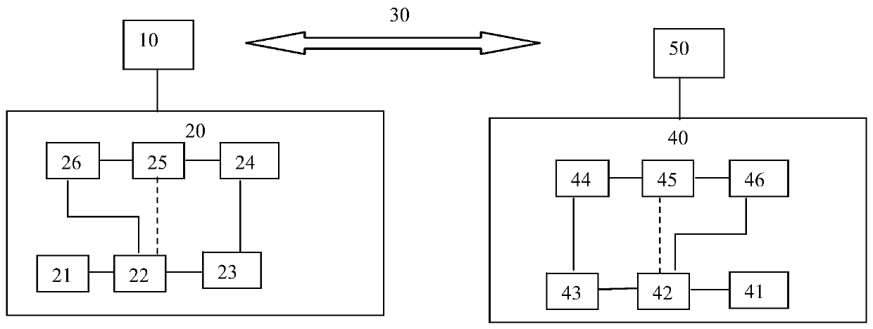
[0045] Such as figure 1 Shown is a schematic diagram of logic modules of the communication device of the present invention.
[0046] The invention provides a stroboscopic information communication device, which at least includes an electric encryption module and an optical modulation module. The electrical encryption module is an encryption chip, and at least one encryption function is selected to convert the electrical signal carrying data information into an encrypted electrical signal. Preferably, the encrypted electrical signal is an encrypted pulse electrical signal.
[0047] The optical modulation module is an optical modulator, which is used to convert electrical signals into optical signals. Optical modulator, also known as electro-optic modulator, is a device that regulates the refractive index, absorption rate, amplitude or phase of the output light. It is based on various forms of electro-optic effect, acousto-optic effect, magneto-optic effect, Frank -Keldgsh ef...
Embodiment 2
[0065] This embodiment is a further improvement on Embodiment 1, and repeated content will not be repeated here.
[0066] This embodiment provides an optical information encryption system, such as figure 1 shown. An optical information encryption system includes an encryption unit 20 and a decryption unit 40 . The encryption unit 20 is connected to the first optical signal transceiving unit 10 . The decryption unit 40 is connected to the second optical signal transceiving unit 50 . The first optical signal transceiving unit 10 and the second optical signal transceiving unit 50 may be directly connected through an optical signal, or may be connected through an optical communication network 30. Preferably, the optical communication network 30 includes one or more of optical fibers, optical isolators and optical communicators. Preferably, the optical fiber may be one or more of standard single-mode optical fiber, dispersion-shifted optical fiber and non-dispersion-shifted opt...
Embodiment 3
[0090] This embodiment is a further improvement on Embodiment 1 and Embodiment 2 and their combination, and the repeated content will not be repeated.
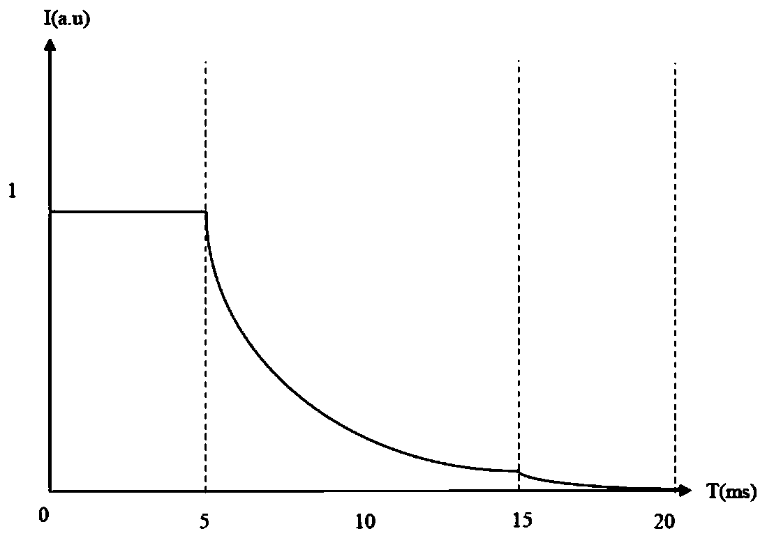
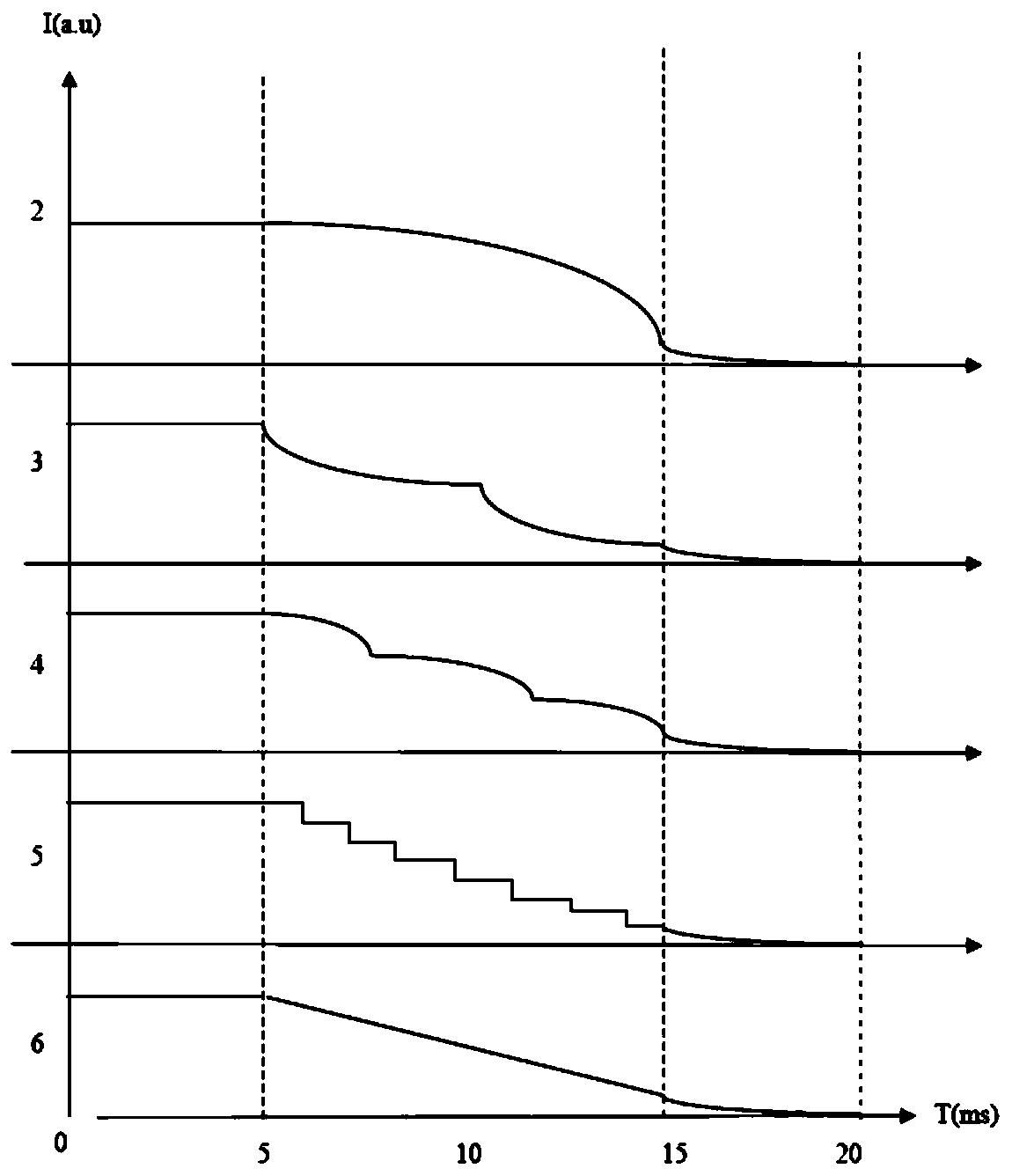
[0091] This example is for Figure 2 to Figure 10 The characteristic curve change of the optical signal is described in detail. The variation trend of the characteristic curve of the preferred first light-emitting stage of the present invention is as follows Figure 2 to Figure 4 shown. The horizontal axis in the figure represents time, and the unit is ms. The vertical axis represents intensity or relative intensity, and the unit is not limited, expressed by the international general symbol a.u. The light-emitting period of this embodiment is preferably 20ms, the first light-emitting stage is 0-5ms, the second light-emitting stage is 5-15ms, and the third light-emitting stage is 15-20ms.
[0092] Such as figure 2 and image 3 In the luminescence curves No. 1-6 shown, the luminous intensity in the first luminescent stage...
PUM
 Abstract
Description
Claims
Application Information
 - R&D
- Intellectual Property
- Life Sciences
- Materials
- Tech Scout
- Unparalleled Data Quality
- Higher Quality Content
- 60% Fewer Hallucinations
Browse by: Latest US Patents, China's latest patents, Technical Efficacy Thesaurus, Application Domain, Technology Topic, Popular Technical Reports.
© 2025 PatSnap. All rights reserved.Legal|Privacy policy|Modern Slavery Act Transparency Statement|Sitemap|About US| Contact US: help@patsnap.com


