
Automatic separating machine adopting zipper numerical control to vertically stop injection molding

A separate machine and automatic technology, applied in the direction of fastener components, other household appliances, household appliances, etc., can solve the problems of zipper CNC machine not being able to accurately inject zippers, plastic waste, increase workload, etc., to achieve cheap replacement and reduce work. Quantity, the effect of saving plastic

Inactive Publication Date: 2018-06-26
天津久泰昇顺科技发展有限公司
View PDF1 Cites 0 Cited by
  • Summary
  • Abstract
  • Description
  • Claims
  • Application Information

AI Technical Summary

Problems solved by technology

[0004] Aiming at the deficiencies in the prior art, the object of the present invention is to provide a zipper numerically controlled upper and lower stop injection molding automatic separation machine to solve the problem that the existing zipper numerical control machine cannot accurately inject on the zipper and needs to be repeatedly debugged, which causes waste of plastic. The problem of increased workload

Method used


Image

  • Automatic separating machine adopting zipper numerical control to vertically stop injection molding
  • Automatic separating machine adopting zipper numerical control to vertically stop injection molding
  • Automatic separating machine adopting zipper numerical control to vertically stop injection molding

Examples


Embodiment Construction

[0017] In order to make the technical means, creative features, goals and effects achieved by the present invention easy to understand, the present invention will be further described below in conjunction with specific embodiments.

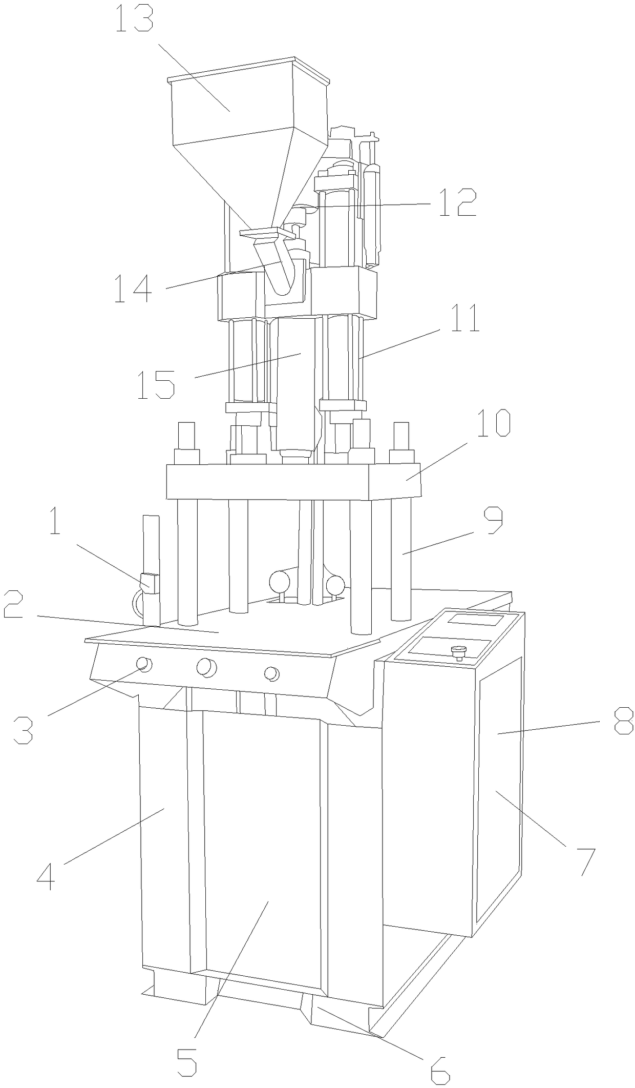
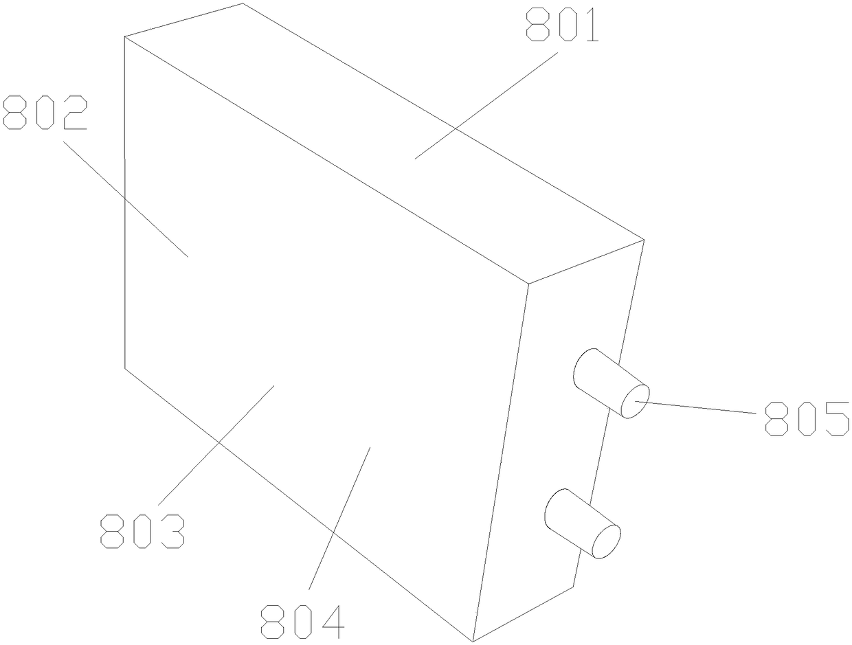
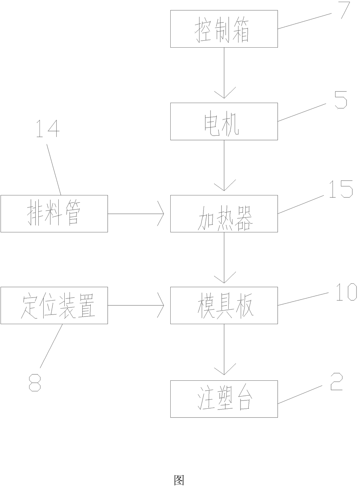
[0018] see Figure 1-Figure 2 , the present invention provides a technical solution: a zipper CNC upper and lower stop injection molding automatic separation machine, its structure includes a sensor 1, an injection molding table 2, a control panel 3, a bed 4, a motor 5, a tripod 6, a control box 7, a positioning Device 8, lifting column 9, mold plate 10, transmission 11, reducer 12, hopper 13, discharge pipe 14, heater 15, the injection molding table 2 is set on the bed 4, and the control panel 3 is fixedly connected Bed 4, the motor 5 is located in the bed 4, the control box 7 is connected with the bed 4, the positioning device 8 is located in the control box 7, the positioning device 8 is composed of a shell 801, a circuit board 802, a regulato...


PUM


Abstract

The invention discloses an automatic separating machine adopting zipper numerical control to vertically stop injection molding. The automatic separating machine is structurally includes a sensor, an injection molding table, a control panel, a lathe bed, a motor, a foot rest, a control box, a locating device, a lifting column, a die plate, a driver, a reducer, a hopper, a discharging pipe and a heater; the injection molding table is arranged on the lathe bed, the control panel is fixedly connected with the lathe bed, and the motor is arranged in the lathe bed; a regulator is arranged on a circuit board, a positioner is connected with the regulator, and a wire socket is fixedly connected with an outer shell; the lifting column is arranged on the injection molding table, the die plate is connected with the lifting column, and the reducer is fixedly connected with the hopper; and the hopper is arranged on the discharging pipe, and the heater is connected with the die plate. According to the automatic separating machine adopting the zipper numerical control to vertically stop the injection molding, the problems that the injection molding cannot be accurately performed on a zipper through an existing zipper numerical control machine, repeated debugging is required, plastic is wasted, and the workload is increased can be solved.

Description

technical field [0001] The invention is a zipper numerical control upper and lower stop injection molding automatic separating machine, which belongs to the field of zipper numerical control. Background technique [0002] Numerical control equipment is a technology that uses computers to realize digital program control. [0003] The prior art discloses an application number: CN201220263219.7, a metal forming wire zipper numerical control tooth pitch automatic rice discharge machine, which includes a main body of the rice discharge machine and a towing mechanism arranged on the main body of the rice discharge machine. The towing mechanism includes There are servo motors and the tow pulley and the pressure pulley that cooperate with each other to drive the movement of the chain tooth cloth to control the tooth pitch. The wheel replaces the traditional way of moving with other mechanisms, so that the pitch of the zipper can be selected randomly, which improves the operating fl...

Claims


Application Information

Patent Timeline
Patent Type & Authority Applications(China)
IPC IPC(8): B29C45/14B29C45/17B29C45/80B29L5/00
CPCB29C45/14065B29C45/17B29C45/80B29C2945/76571B29C2945/76732B29L2005/00
Inventor 马丽
Owner 天津久泰昇顺科技发展有限公司
Learn More