
Metal tag printer

A technology for printers and signs, applied in typewriters, printing devices, printing, etc., can solve the problems of low printing efficiency and inconvenient operation.

Pending Publication Date: 2018-06-26
TIANJIN XUYANGBENHUA SCI & TECH CO LTD
View PDF6 Cites 3 Cited by
  • Summary
  • Abstract
  • Description
  • Claims
  • Application Information

AI Technical Summary

Problems solved by technology

The existing metal signage printers have low printing efficiency and inconvenient operation

Method used


Image

  • Metal tag printer

Examples


Embodiment Construction

[0008] In order to make the technical means, creative features, goals and effects achieved by the present invention easy to understand, the present invention will be further described below in conjunction with specific embodiments.

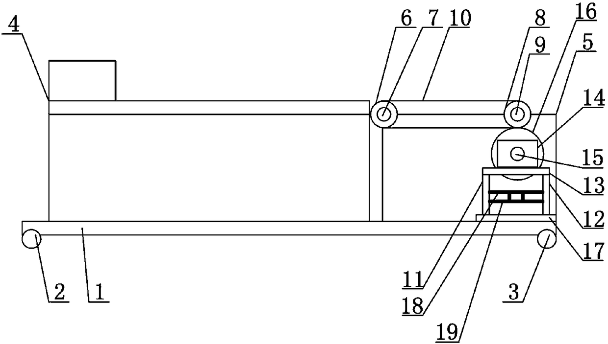
[0009] Such as figure 1 As shown, a metal signage printer includes a base plate 1, a pair of first moving wheels 2 is provided on one side of the bottom of the base plate 1, and a pair of second moving wheels 3 is provided on the other side of the bottom of the base plate 1, and the second moving wheels 3 and The shape and size of the first moving wheel 2 are the same; the base plate 1 is provided with a metal label printer main body 4, and the base plate 1 is provided with a frame 5, and the frame 5 is arranged on the side wall position of the metal label printer main body 4, and the frame 5 is provided with Driven wheel 6 is arranged, and driven wheel 6 is installed on the frame 5 by the first mounting shaft 7, is provided with driving wheel 8 o...


PUM


Abstract

The invention discloses a metal tag printer which comprises a bottom plate. A metal tag printer body is arranged on the bottom plate. A rack is arranged on the bottom plate and is arranged at the position of the side wall of the metal tag printer body. A driven wheel is arranged on the rack. A driving wheel is arranged on the rack. A conveying belt is arranged between the driven wheel and the driving wheel. A first side plate and a second side plate are arranged at the inner bottom of the rack. A carrier plate is arranged between the end of the first side plate and the end of the second side plate and provided with a drive motor. A drive shaft is arranged on the front portion of the drive motor. A drive wheel is arranged at the end of the drive shaft and engaged with the driving wheel. Bymeans of the metal tag printer, the printing efficiency can be greatly improved.

Description

technical field [0001] The invention relates to a printer, in particular to a metal label printer. Background technique [0002] Metal signage printer is an inkjet printing high-tech digital printing equipment, so it can not be limited by any material, can be printed on wood, glass, crystal, metal plate, floor tiles, tiles, CDs, acrylic, plexiglass, EVA.KT board, leather, silicone, plastic, PP, PE, PVC, cloth, signage, stone and other surfaces for color photo-level printing. Whether it is a simple block color pattern, a full-color pattern or a pattern with excessive color, it can be printed at one time without plate making, printing and repeated coloring. The color is beautiful and the effect is realistic. Strong wear adhesion, no fading, easy machine operation and stable performance, creating higher printing quality than traditional methods, fully meeting the high-intensity mass production requirements of various industries, thereby significantly improving the market compe...

Claims


Application Information

Patent Timeline
IPC IPC(8): B41J3/407B41J3/413B41J13/00
CPCB41J3/407B41J3/413B41J13/00
Inventor 任绪
Owner TIANJIN XUYANGBENHUA SCI & TECH CO LTD
Learn More