Supercharge Your Innovation With Domain-Expert AI Agents!

elevator system

A technology of an elevator system and a driving device, which is applied in the field of elevators, can solve problems such as limiting the applicable range of counterweight weight and affecting the coping ability of the elevator system, and achieve the effects of merging components, reducing costs, and improving stability

Active Publication Date: 2019-10-18
SHANGHAI MITSUBISHI ELEVATOR CO LTD
View PDF7 Cites 0 Cited by
  • Summary
  • Abstract
  • Description
  • Claims
  • Application Information

AI Technical Summary

Problems solved by technology

Therefore, such an arrangement has obvious restrictions on the height space of the counterweight, which also limits the applicable range of the counterweight, making the counterweight the bottleneck of the elevator system and seriously affecting the coping ability of the elevator system.

Method used


Image

  • elevator system
  • elevator system
  • elevator system

Examples


Embodiment 1

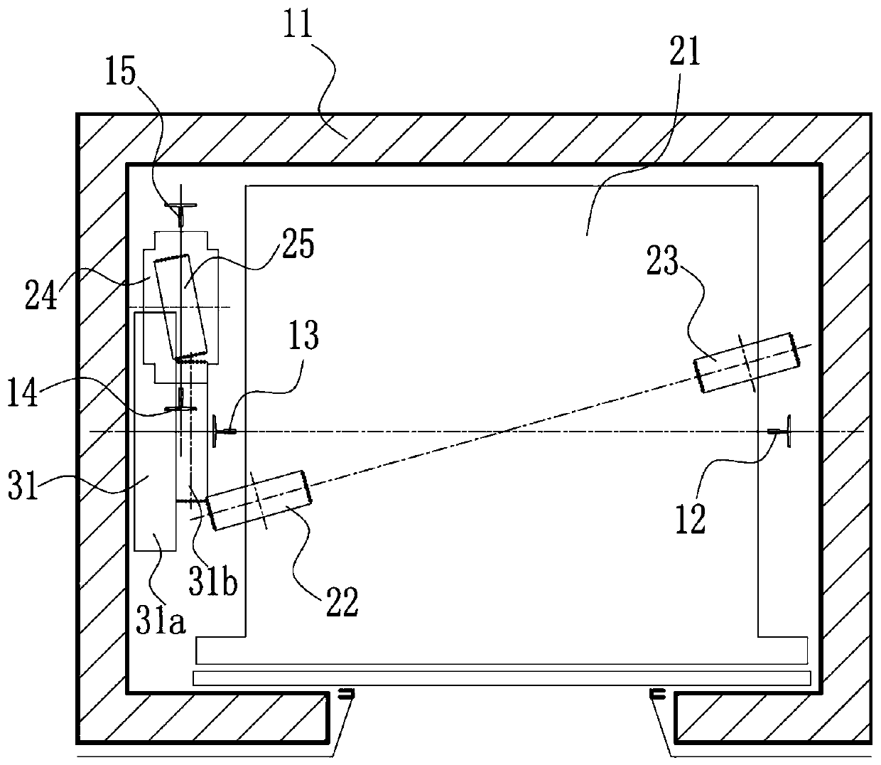
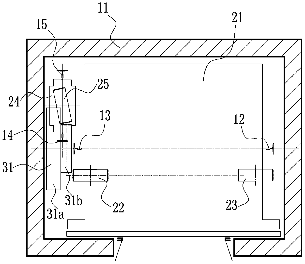
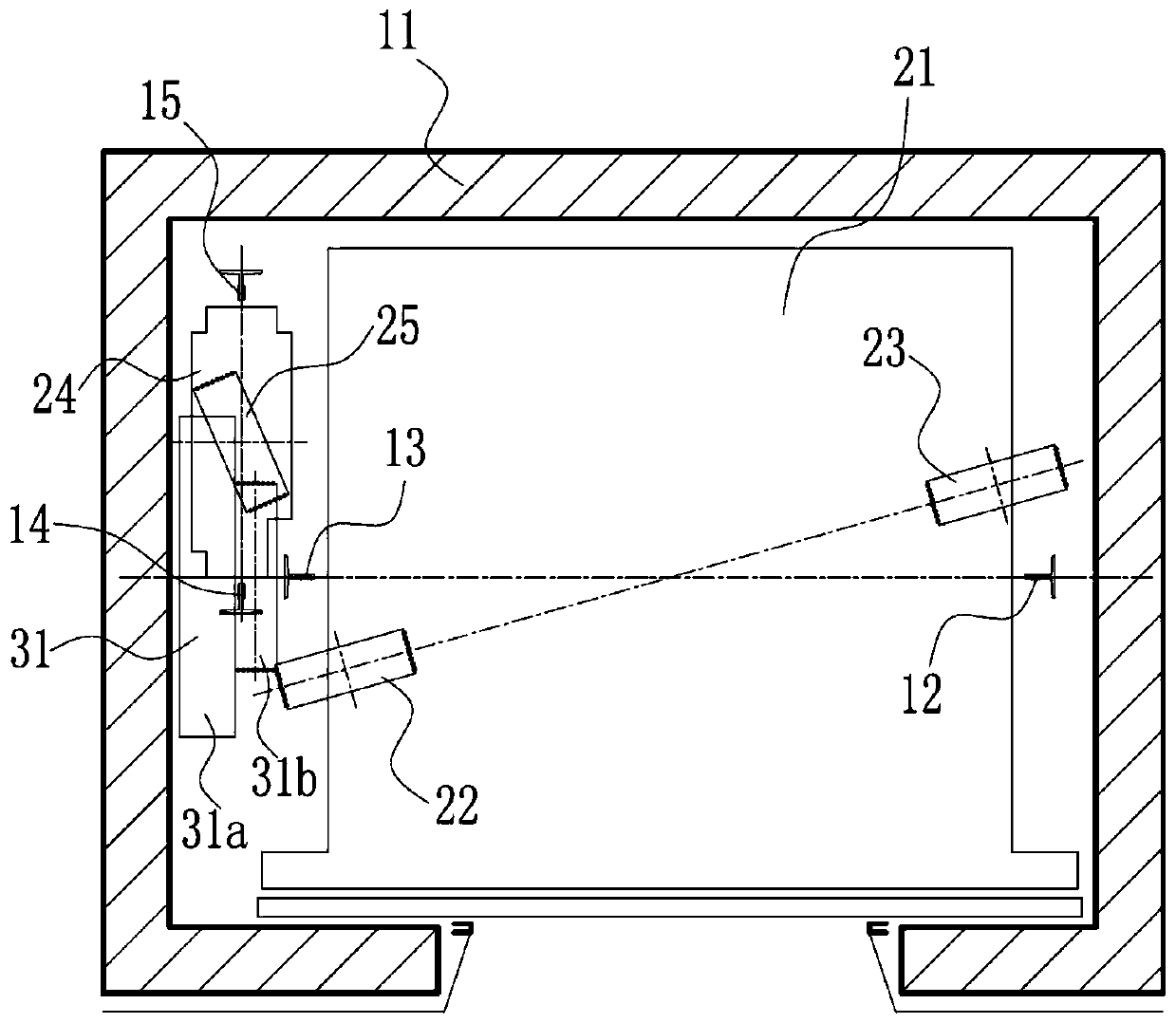
[0051] Such as Figure 1 to Figure 5 As shown, the elevator system includes an elevator passage 11, a car 21, a driving device 31, a counterweight 24, a traction rope 53, a support seat 41, a counterweight side rope head seat 42, a pair of car guide rails 12,13 and a Counterweight guide rails 14,15; car 21, driving device 31, counterweight block 24, support seat 41, car guide rails 12,13 and counterweight guide rails 14,15 are all arranged in the lifting passage 11; The block 24 and the pair of counterweight guide rails 14 and 15 are located on the same side of the car 21; the car 21 and the counterweight block 24 are connected by a traction rope 53; , 13 moves vertically, and simultaneously drives the counterweight 24 to move vertically along the pair of counterweight guide rails 14, 15;

[0052] Such as Figure 4 , Figure 5 As shown, the support base 41 is installed on a car guide rail 13 on the side of the car 21 and a counterweight guide rail 14 closest to the car guid...

Embodiment 2

[0059] Based on the elevator system of Embodiment 1, in the vertical direction of the hoistway 11 , the installation surface of the counterweight-side rope end seat 42 is higher than the installation surface of the support seat 41 .

[0060] Preferably, in the vertical direction of the lifting channel 11 , the counterweight 24 is located below the supporting seat 41 of the driving device 31 . The highest position that the counterweight 24 can reach is still lower than the support base 41 .

[0061] Such as Figure 4 to Figure 9 As shown, the counterweight side rope head 51 is installed on the counterweight side rope head seat 42, and a rope spring 51a is arranged above the counterweight side rope head seat 42. Below the counterweight side rope head seat 42, the counterweight side rope head seat 42 The rope head 51 also extends the rope head rod 51b of a certain length, the rope head taper sleeve 51c, and the rope head clamping device 52 is also installed below it, and the cou...

Embodiment 3

[0063] Based on the elevator system of embodiment one, such as Figure 4 to Figure 7 As shown, the counterweight-side rope end seat 42 is installed on the support seat 41 of the driving device 31 and the counterweight guide rail 15 farthest from the car guide rail 13 through the mounting pieces 43 and 44 .

[0064] In the elevator system of Embodiment 3, the counterweight-side rope head seat 42, the support seat 41 of the driving device 31 and the counterweight guide rail 15 farthest from the car guide rail 13 form an integral frame structure, and the structure is stronger.


PUM


Abstract

The invention discloses an elevator system. A supporting seat is installed on a car guide rail on one side of a car and a counterweight guide rail closest to the car guide rail. A driving device is installed on the supporting seat. The rope end on the counterweight side of a haulage rope is installed on a counterweight side rope end seat. The counterweight side rope end seat is installed on the supporting seat through an installing part. According to the elevator system, the driving device is arranged by sufficiently using the space of a lift way, a stable triangular structure is formed by thesupporting seat, the car guide rails and the counterweight guide rails, improvement on the stability of the supporting seat is facilitated, and the elevator system is better in safety, beneficial forreducing elevator vibration and beneficial for reducing the load bearing requirement of each single guide rail. The counterweight side rope end seat and the supporting seat form an integral frame structure so as to achieve the effects of component combination and simplification, the installing process can be implemented at one go, there is no need for separately positioning and installing the supporting seat and the counterweight side rope end seat, and installing and adjusting are facilitated.

Description

technical field [0001] The invention relates to elevator technology, in particular to an elevator system. Background technique [0002] In traditional elevators driven by traction sheaves, the mechanical room where the driving device and control equipment are placed often occupies the top space of the building required by the elevator, and there are many restrictions on the layout of the mechanical room. This not only affects the space utilization rate and aesthetic effect of the building, but also increases the construction cost. With the advent of machine room-less elevator technology, the problems of traditional traction sheave-driven elevators have been resolved. [0003] In a disclosed patent (notification number CN 1081162C, date of announcement on March 20, 2002), the elevator mechanical equipment is installed on the longitudinal side of one of the car or the counterweight guide rail. The guide rail is used as a structural member to reinforce the mechanical strength...

Claims


Application Information

Patent Timeline
Patent Type & Authority Patents(China)
IPC IPC(8): B66B11/00B66B11/08
Inventor 李丰童正国金川
Owner SHANGHAI MITSUBISHI ELEVATOR CO LTD
Features
  • R&D
  • Intellectual Property
  • Life Sciences
  • Materials
  • Tech Scout
  • Unparalleled Data Quality
  • Higher Quality Content
  • 60% Fewer Hallucinations
Learn More