
Object detection device

A technology for object detection and objects, which is applied in the direction of measuring devices, radio wave measuring systems, instruments, etc., can solve the problems of increased manufacturing costs of object detection devices, increased size of object detection devices, etc., and achieve the effect of suppressing the increase in size

Inactive Publication Date: 2018-06-26
OMRON AUTOMOTIVE ELECTRONICS CO LTD
View PDF8 Cites 1 Cited by
  • Summary
  • Abstract
  • Description
  • Claims
  • Application Information

AI Technical Summary

Problems solved by technology

As a result, the size of the object detection device may be further increased
In addition, the increase in the number of components of the light-emitting part and the light-receiving part increases the manufacturing cost of the object detection device

Method used


Image

  • Object detection device
  • Object detection device
  • Object detection device

Examples


Embodiment Construction

[0031] The embodiments of the present disclosure will be described below with reference to the drawings. In the drawings, the same or corresponding parts are denoted by the same reference numerals. In the embodiments of the present disclosure, in order to provide a more thorough understanding of the present invention, a large number of specific details are explained. However, it will be apparent to those of ordinary skill in the art that the present invention can be practiced without these specific details. In other cases, well-known features have not been described in detail to avoid obscuring the present invention.

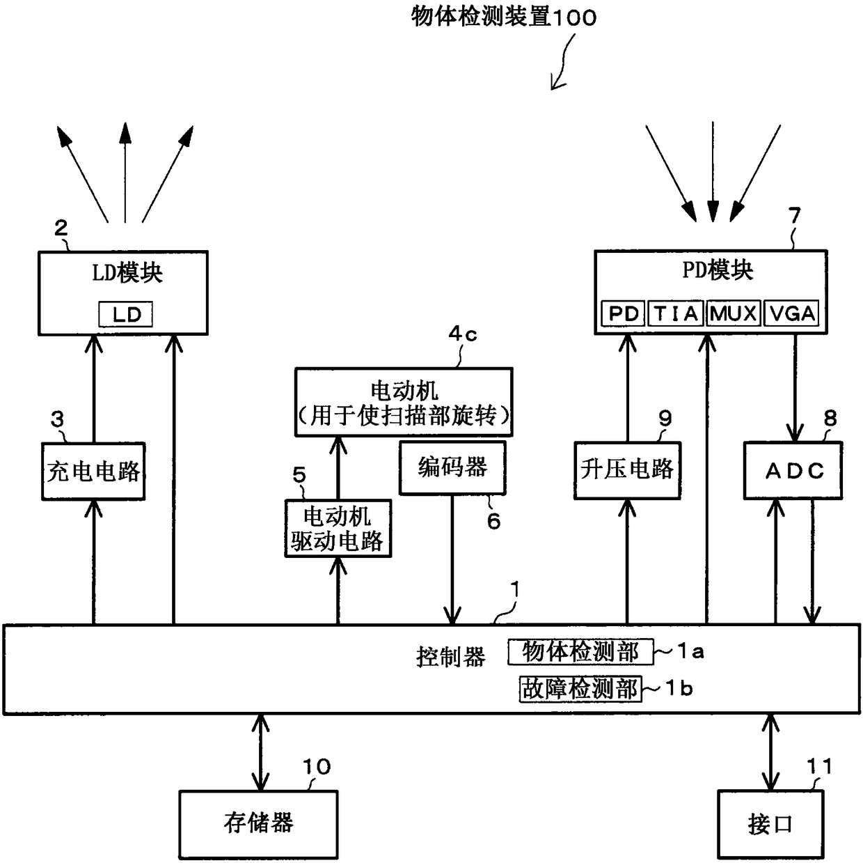
[0032] First, refer to figure 1 The electrical configuration of the object detection device 100 in one or more embodiments of the present disclosure is described.

[0033] figure 1 This is an electrical configuration diagram of the object detection device 100. The object detection device 100 is a lidar used in vehicles. The controller 1 is composed of a CPU and t...


PUM


Abstract

An object detection device includes: a light emitter; a light receiver; a rotating scanner having a mirror and reflecting light from the light emitter off the mirror by rotating the mirror to scan thereflected light over a predetermined range, and reflecting light reflected off a target off the mirror to guide the reflected light to the light receiver; an object detector detecting whether there is a target, based on a light reception signal; a light guider guiding light from the light emitter to the light receiver; and a failure detector detecting whether there is a failure, based on a lightemission state of the light emitter and a light reception state by the light receiver. The light guider receives light emitted from the light emitter and reflected off the mirror, and reflects the light off the mirror to guide the reflected light to the light receiver.

Description

[0001] Cross references to related applications [0002] This application is based on Japanese Patent Application No. 2016-246601 filed with the Japan Patent Office on December 20, 2016, and the entire content of the application is incorporated herein by reference. Technical field [0003] The present disclosure relates to an object detection device that detects an object by projecting and receiving light, and more particularly relates to self-diagnosis of a failure in an optical system. Background technique [0004] An object detection device (such as a lidar for a vehicle) projects light from a light emitting part within a predetermined range, and detects whether there is an object based on the result of the reflected light of the projected light received by the light receiving part (for example, JP2002-31685A, JP2010 -204015A, JPH10-31064A, JP2014-145744A and WO2016 / 012579A). In addition, there is also an object detection device that detects the distance from the object detectio...

Claims


Application Information

Patent Timeline
IPC IPC(8): G01S7/481G01S17/93
CPCG01S7/4817G01S17/931G01S17/42G01S7/4818G01S7/497G01S17/08
Inventor 大谷直辉板尾大助横田求一柳星文
Owner OMRON AUTOMOTIVE ELECTRONICS CO LTD
Features
  • Generate Ideas
  • Intellectual Property
  • Life Sciences
  • Materials
  • Tech Scout
  • Unparalleled Data Quality
  • Higher Quality Content
  • 60% Fewer Hallucinations
Learn More