
Lamp control device and lamp lighting system

A technology for control devices and lamps, which is applied in signal devices, transportation and packaging, pulse technology, etc. It can solve problems such as wrong lighting of lamps and leakage current lamps, and achieve the effect of preventing wrong lighting of lamps and suppressing size increase

Active Publication Date: 2018-12-21
MITSUBA CORP
View PDF6 Cites 0 Cited by
  • Summary
  • Abstract
  • Description
  • Claims
  • Application Information

AI Technical Summary

Problems solved by technology

[0004] In addition, in the lamp lighting system, the turn signal switch may be turned on due to, for example, rainwater or dirt, so that a leakage current may flow to the lamp side, and the lamp may be erroneously turned on at a timing not intended by the user.

Method used


Image

  • Lamp control device and lamp lighting system
  • Lamp control device and lamp lighting system
  • Lamp control device and lamp lighting system

Examples


Embodiment approach 1

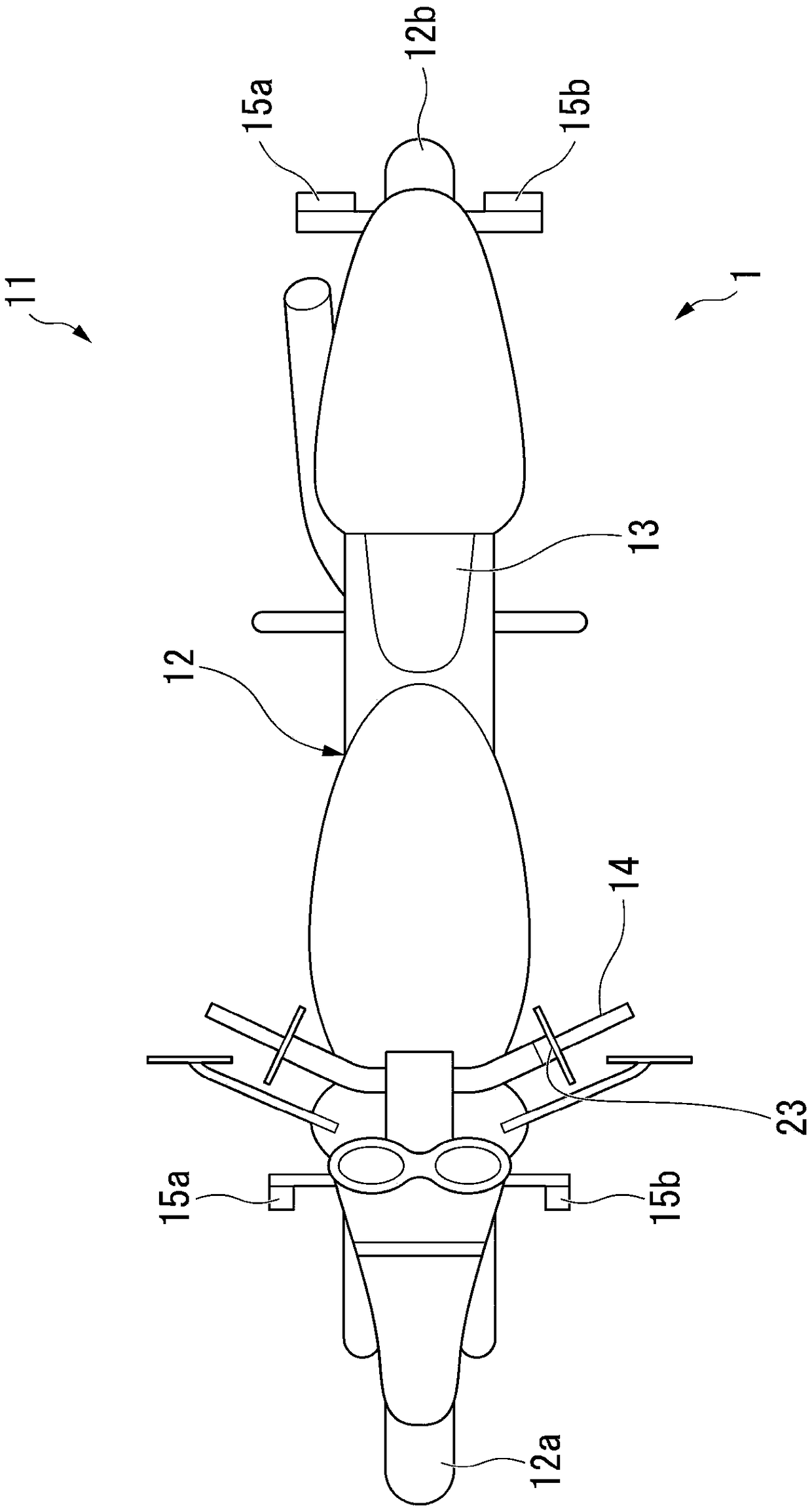
[0043] figure 1 It is a plan view schematically showing a motorcycle equipped with the lamp lighting system 1 in Embodiment 1. FIG. Such as figure 1 As shown, a front wheel 12a and a rear wheel 12b are provided on a vehicle body 12 of a motorcycle 11 as a vehicle. A driver seated on a seat 13 provided at the center of the vehicle body 12 operates the handle 14 to drive the motorcycle 11 .

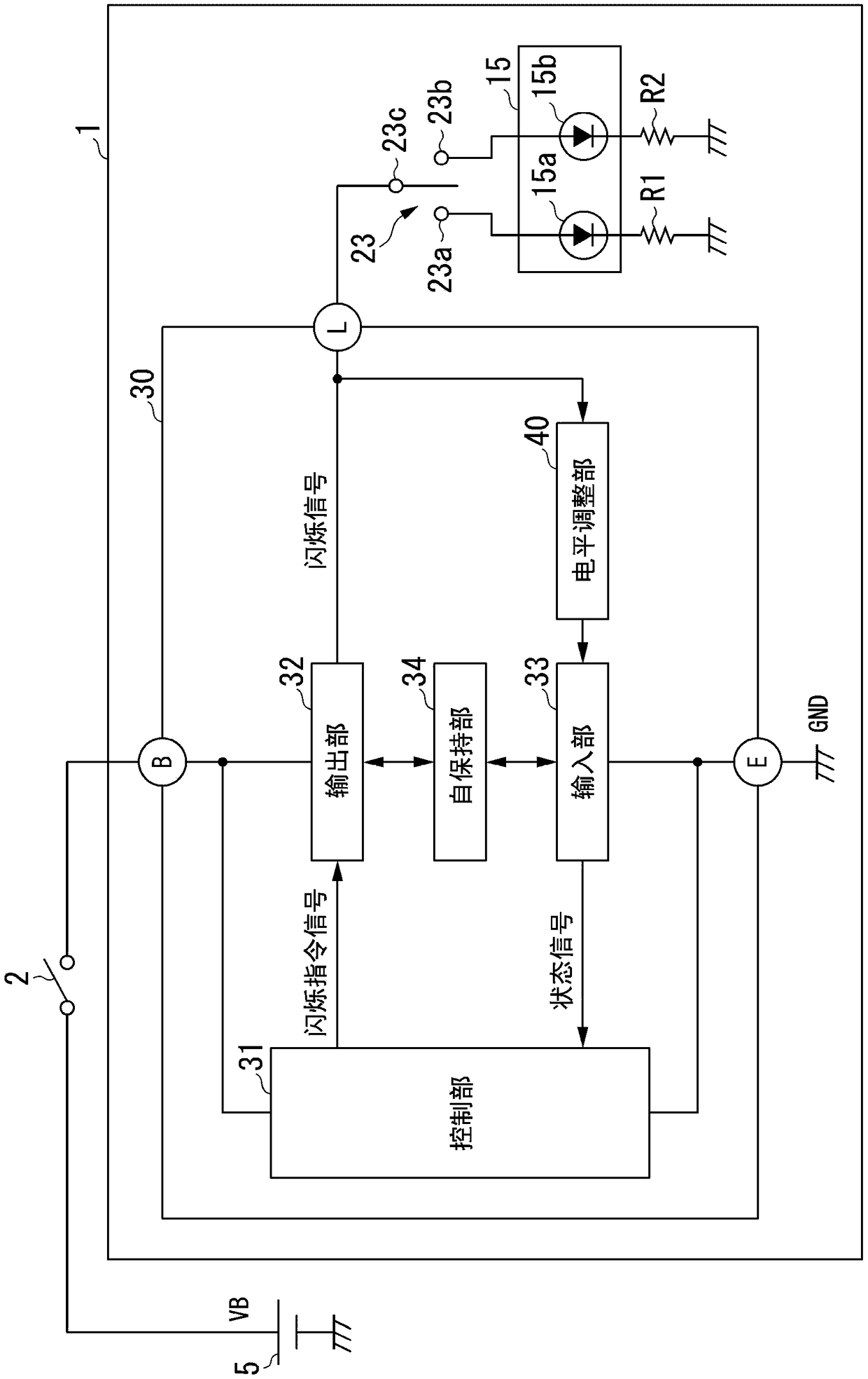
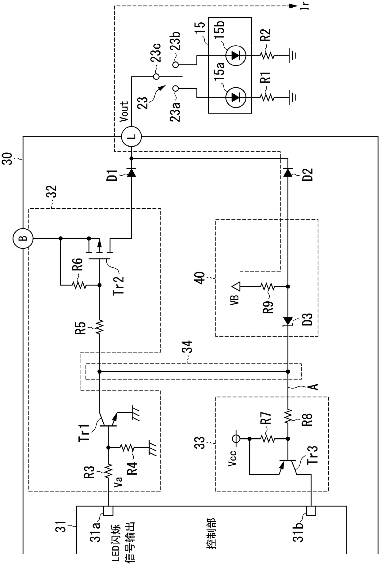
[0044] figure 2 It is a diagram showing an example of a schematic configuration of the lamp lighting system 1 in the first embodiment.

[0045] Such as figure 1 with figure 2As shown, the lamp lighting system 1 includes: a lamp 15 , a display switch 23 and a lamp control device 30 .

[0046] Such as figure 1 As shown, right side turn signal lamps 15 a serving as lamps 15 are provided on the front and rear right sides of the vehicle body 12 . Further, on the front and rear left sides of the vehicle body 12 , a left turn signal lamp 15 b as a lamp 15 is provided. In addition, i...

Embodiment approach 2

[0090] Figure 5 It is a diagram showing an example of a schematic configuration of the lamp lighting system 1A in the second embodiment. The lamp lighting system 1A of the second embodiment has a configuration in which the leakage current detection performance of the level adjustment unit 40 is further improved compared to the first embodiment.

[0091] The lamp lighting system 1A includes a lamp 15, a display switch 23, a lamp control device and a bias resistor RB.

[0092] Hereinafter, a circuit example of the lamp lighting system 1A in Embodiment 2 will be described. Figure 5 It is a diagram showing a circuit example of the lamp lighting system 1A in the second embodiment.

[0093] In the lamp lighting system 1 according to Embodiment 1, it is desirable that the lamp 15 is not erroneously turned on even when seawater, rainwater, etc. enter the display switch 23 and the resistance value of the insulation resistance becomes low. That is, even when seawater or rainwater e...


PUM


Abstract

A lamp control device controls, in conjunction with an operation of a display switch that is provided to a vehicle, the flashing of a lamp that is provided to the vehicle. The lamp control device comprises: an output unit that, on the basis of a flash command signal directing the flash timing of the lamp, outputs a flash signal to the lamp from an output terminal for driving, said flash signal causing the lamp to flash; an input unit that outputs a state signal of a first logic if a signal level from the output terminal for driving is a first level, said state signal indicating that the stateof the display switch is an on state, and outputs a state signal of a second logic if the signal level is a second level that is different from the first level, said state signal indicating that the state of the display switch is an off state; a control unit that outputs the flash command signal to the output unit if the logic of the state signal outputted from the input unit is the first logic; and a self-maintenance unit that, if the lamp is in a flashing state, maintains the logic of the state signal on the basis of the logic of the flash command signal.

Description

technical field [0001] The invention relates to a lamp control device and a lamp lighting system. [0002] This application claims priority based on Patent Application No. 2016-110159 filed in Japan on June 1, 2016 and Patent Application No. 2016-110160 filed in Japan on June 1, 2016, and the contents thereof are cited here. Background technique [0003] Conventionally, there has been known a lighting system for lighting a lamp, in which by operating a turn signal switch mounted on a vehicle, a turn signal lamp (lamp) corresponding to the operated turn signal switch is blinked, thereby notifying the surroundings of the vehicle's advancing direction ( For example, refer to Patent Document 1). [0004] In addition, in the lamp lighting system, the turn signal switch may be turned on due to, for example, rainwater or dirt, so that a leakage current may flow to the lamp side, and the lamp may be erroneously turned on at a timing not intended by the user. Therefore, in the lamp...

Claims


Application Information

Patent Timeline
IPC IPC(8): B60Q1/38B60Q1/34
CPCB60Q1/38H05B47/10H03K2217/0063H03K17/6877B60Q1/34
Inventor 柳田雄一石田昌克小林一行
Owner MITSUBA CORP
Features
  • Generate Ideas
  • Intellectual Property
  • Life Sciences
  • Materials
  • Tech Scout
  • Unparalleled Data Quality
  • Higher Quality Content
  • 60% Fewer Hallucinations
Learn More