Optical scanning apparatus and image forming apparatus including the same
A technology of optical scanning and optical box, applied in the direction of optics, optical components, instruments, etc., can solve the problem of increasing the size of imaging equipment, and achieve the effect of suppressing the increase in size
- Summary
- Abstract
- Description
- Claims
- Application Information
AI Technical Summary
Problems solved by technology
Method used
Image

Examples
no. 1 example
[0029] Overall structure of imaging device 100
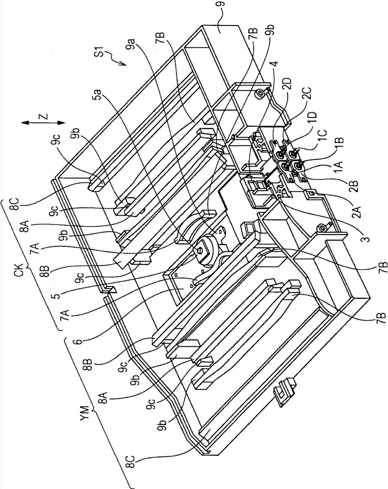
[0030] The image forming apparatus 100 according to the present embodiment functions as a color laser printer. The overall structure of the imaging device 100 will be described. Figure 16 is a schematic sectional view of the imaging apparatus 100 . The image forming apparatus 100 mainly includes four photosensitive drums 80 (80a, 80b, 80c, and 80d) as photoreceptors, an optical scanning device S1, an intermediate transfer belt 90, a feed cassette 91, a fixing unit 95, and a secondary transfer roller 94 . Around the respective photosensitive drums 80 of the image forming apparatus 100 are arranged charging rollers 81 (81a, 81b, 81c, and 81d), developing rollers 82 (82a, 82b, 82c, and 82d), and primary transfer rollers 83 (83a, 83b, 83c and 83d), which serve as processing units for processing the photosensitive drum 80.
[0031] An optical scanning device S1 serving as an exposure unit is arranged below the photosensitive dru...
no. 2 example
[0083] A second embodiment will now be described. Components similar to those of the first embodiment are denoted by the same reference numerals, and thus descriptions thereof are omitted.
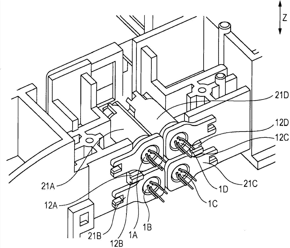
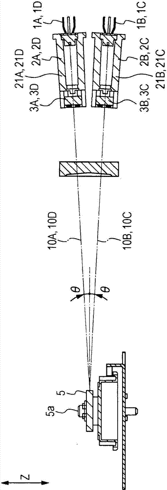
[0084] Figure 13A is a perspective view of the optical box 109. While four light source units 21 are positioned relative to a single optical box 9 in the first embodiment, two light source units 21 ( 21A and 21B) are positioned relative to the optical box 109 in the second embodiment. Therefore, only one optical scanning system is supported on one side of the rotating polygon mirror 5 in the optical box 109 . Figure 13B The surrounding areas of the contact portions 31A, 31B, 32A, 32B, 51A, 51B, 52A, and 52B of the optical box 109 viewed from the optical axis direction are shown. When the two light source units 21A and 21B are positioned by a single optical box 109 , an effect similar to that of the first embodiment can be obtained by forming the abutment portions 31A to 52B on the pos...
PUM
 Abstract
Description
Claims
Application Information