Fuel cell system

A fuel cell system and fuel cell stack technology, which is applied to fuel cells, fuel cell additives, power system fuel cells, etc., can solve the problems of increasing the size of the fuel cell system, and achieve the goal of suppressing the increase in size and supplying efficiently. Effect

Pending Publication Date: 2021-07-09
TOYOTA JIDOSHA KK
View PDF0 Cites 0 Cited by
  • Summary
  • Abstract
  • Description
  • Claims
  • Application Information

AI Technical Summary

Problems solved by technology

However, providing the bypass flow path increases the size of the fuel cell system

Method used


Image

  • Fuel cell system
  • Fuel cell system
  • Fuel cell system

Examples


no. 1 example

[0032] [Schematic Configuration of Fuel Cell System]

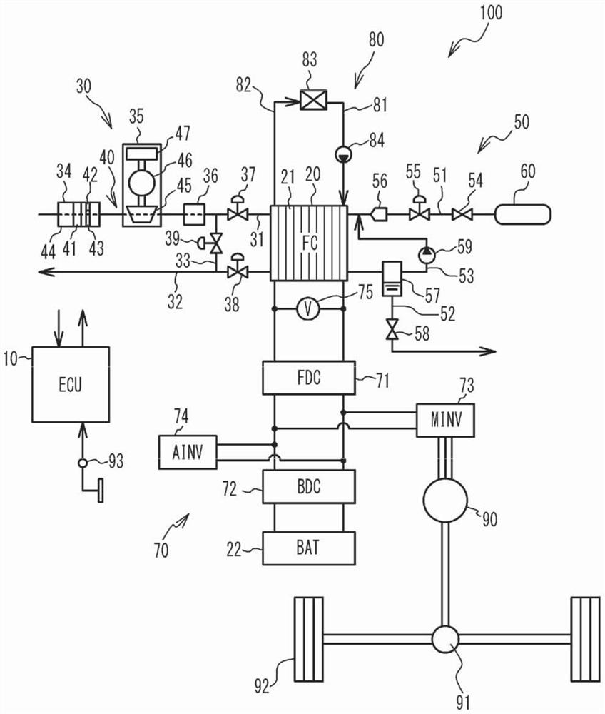
[0033] figure 1 is a schematic diagram of the fuel cell system according to the first embodiment mounted on a vehicle. refer to figure 1 , the fuel cell system 100 includes an electronic control unit (ECU) 10, a fuel cell stack (hereinafter referred to as FC) 20, a secondary battery (hereinafter referred to as BAT) 22, an oxidant gas system 30, a fuel gas system 50, Power system 70 and cooling system 80 . In addition, the vehicle includes an electric motor 90 for running, a transmission 91 , wheels 92 , and an accelerator opening sensor 93 . The vehicle travels by driving the motor 90 using the FC 20 and the BAT 22 as power sources.

[0034] FC 20 receives fuel gas and oxidant gas to generate electricity. The FC 20 includes a stacked unit cell 21 of solid polymer electrolyte type. The unit cell 21 includes: a membrane electrode assembly which is a power generator in which electrodes are arranged on both surfaces of a...

no. 2 example

[0080] Figure 8 is a schematic diagram of a fuel cell system according to a second embodiment mounted on a vehicle. refer to Figure 8 , in the fuel cell system 200 according to the second embodiment, the air compressor 35 , the air cleaner 34 , and the intercooler 36 are arranged in this order from the upstream side of the flow of the oxidant gas flowing through the air supply pipe 31 . Other components are the same as those in the first embodiment, and thus descriptions thereof are omitted.

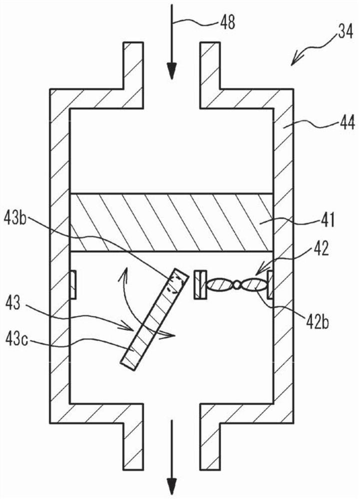
[0081] As described above, the first embodiment shows the air compressor 35 disposed at the downstream side of the flow of the oxidant gas with respect to the fan 42 and the switching valve 43 . However, in the second embodiment, the air compressor 35 is provided at the upstream side of the flow of the oxidant gas with respect to the fan 42 and the switching valve 43 . Likewise, in the second embodiment, the on-off valve 43 is opened due to the force generated by driving the air com...

no. 3 example

[0083] The third embodiment differs from the first embodiment in that the on-off valve 43 is a solenoid valve or an electric valve, and the opening and closing of the on-off valve 43 is controlled according to an instruction from the controller 10 . Other components are the same as those in the first embodiment, and thus descriptions thereof are omitted.

[0084] [Intermittent operation control of ECU]

[0085] Figure 9 is a flowchart showing an example of intermittent operation control of the ECU in the third embodiment. and Figure 5 Similar to the control shown in the first embodiment, Figure 9 The control shown in starts with the power generation operation in which the required power of the FC 20 is higher than the predetermined power and the FC 20 performs power generation. refer to Figure 9 , the ECU 10 executes with Figure 5 Steps S10 and S12 in the first embodiment are the same as steps S40 and S42. After step S42, the ECU 10 instructs the on-off valve 43 to...


PUM


Abstract

The invention relates to a fuel cell system. The fuel cell system includes a fuel cell stack, a first discharger, an opening-and-closing valve, a second discharger, a voltage detector, and a controller, wherein the opening-and-closing valve and the first discharger are arranged side by side in a direction intersection a flow of the oxidant gas; a discharge pressure of the second discharger is higher than that of the first discharger; the controller is configured to control the first and second dischargers; the controller is configured to drive the second discharger in a state where the opening-and-closing valve opens, in a power generation operation in which required power to the fuel cell stack generates power and the required power of the fuel cell stack is higher than the preset power; the controller is configured to stop the second discharger when an intermittent operation in which the required power is equal to or lower than the predetermined power is switched from the power generation operation, and to drive the first discharger when the voltage of the fuel cell stack is equal to or lower than the first predetermined voltage in the intermittent operation in a state where the opening-and-closing valve closes.

Description

technical field [0001] The invention relates to a fuel cell system. Background technique [0002] There is known an intermittent operation in which the power generation of the fuel cell stack is temporarily stopped by using the power of the secondary battery when the required power of the fuel cell stack is equal to or lower than a predetermined power. In this intermittent operation, the oxidant gas is supplied to the fuel cell stack so that the voltage of the fuel cell stack does not exceed a range between a predetermined upper limit voltage and a lower limit voltage. When supplying the oxidant gas to the fuel cell stack, a compressor and a blower selectively used according to the required power of the fuel cell stack are known, and the compressor and the blower are provided in a gas flow path through which the oxidant gas flows (for example, , see Japanese Unexamined Patent Application Publication No. 2005-259692). [0003] The power generation operation in which the fue...

Claims


Application Information

Patent Timeline
IPC IPC(8): H01M8/04082H01M8/04089H01M8/04111H01M8/04537H01M8/04955H01M8/2457
CPCH01M8/2457H01M8/04955H01M8/04089H01M8/04201H01M8/04559H01M8/04111H01M2250/20H01M16/006H01M8/04164H01M8/04097H01M8/04029H01M8/04619H01M8/04753H01M8/04768B60L50/72B60L58/31B60L58/33Y02T90/40Y02E60/10Y02E60/50
Inventor 森永礼
Owner TOYOTA JIDOSHA KK
Why Eureka
Try Eureka