Container

a technology of container and stoke, which is applied in the field of container, can solve the problems of low productivity, the need to replace oxidized and corroded stoke, and achieve the effects of high heat conductivity, effective prevention of clogging of the flow passage, and high heat conductivity

Inactive Publication Date: 2007-04-17
HOEI SHOKAI CO LTD
View PDF12 Cites 57 Cited by
  • Summary
  • Abstract
  • Description
  • Claims
  • Application Information

AI Technical Summary

Benefits of technology

[0020]According to the present invention, since the flow passage for the molten metal is formed with a fire resistant wall that has high heat conductivity that surrounds the inner wall of the main body of the container, when the molten metal is loaded to the container, heat from the molten metal is conducted to the fire resistant wall, therefore, the temperature of the flow passage becomes almost equal to that of the molten metal. Likewise, when inside of the container is preheated, the flow passage is heated effectively through the fire resistant wall being the route for the thermal conduction. Thus, when the molten metal that flows inside the flow passage is not cooled therewith, the molten metal does not solidify at the front surface of the flow passage, nor does the molten metal attaches thereto. In other words, when the molten metal solidifies and attaches to the flow passage, the passage tends to get clogged (as in a conventional pipe). In contrast, according to the present invention, the flow passage can be prevented effectively from getting clogged. In addition, according to the present invention, since the temperature of the flow passage becomes almost equal to the temperature of the molten metal, the viscosity of the molten metal that flows near the front surface of the flow passage does not decrease, enabling the molten metal to be supplied from the container or loaded into the container with a smaller pressure difference than before. In other words, in the container according to the present invention, the flow passage for the molten metal is made of a fire resistant wall that has a high heat conductivity and that surrounds the inner wall of the container so that the temperature of the flow passage becomes almost equal to the temperature of the molten metal stored in the container. Thus, the present invention is very effective for a system that loads the molten metal to a container and loads the molten metal therefrom using a pressure difference.
[0021]Since the container according to the present invention has a through-hole for adjusting an inner pressure, when the inside of the container is applied with a negative pressure through the through-hole, the molten metal can be loaded to the container through the flow passage. According to the present invention, since the hot molten metal is loaded to the container through the flow passage in the foregoing manner, the molten metal cleans the metal that is attached to the front surface of the flow passage. Thus, due to the through-hole for adjusting an inner pressure provided in the present invention, the clogging can be prevented effectively.
[0022]The container according to one form of the present invention further comprises a heat insulation member disposed between the inner wall of the main body of the container and the fire resistant wall. Since the whole container should have high degree of heat insulation, an insulation member of high heat insulation is lined. In addition, a portion that directly contacts the molten metal is lined with a refractory member. In the container according to the present invention, a fire resistant caster material is disposed in a zone that separates the inside of the container from the flow passage. The heat conductivity of the area is intentionally and relatively designed larger than that of the other area. The density and the heat conductivity of the refractory member are designed so that they are larger than those of the heat insulation member. As an example of the refractory member, there is a dense fire resistant caster. As examples of the heat insulation member, there are a heat insulation caster and board materials. Since the container is structured in such a manner, In addition that the molten metal stored in the container is heat-insulated, heat can easily be conducted to the foregoing flow passage. Thus, the flow passage can be sufficiently prevented from being cooled from the outside. As a result, the flow passage can be more effectively prevented from getting clogged than before. In addition, since the viscosity of the molten metal can be kept low, the molten metal can be loaded to and supplied from the container with a small pressure difference.
[0023]In the container according to an embodiment of the present invention, the bottom portion of the main body of the container is tilted toward the opening so that the opening is at a low position. With this configuration, when the amount of the molten metal in the container becomes small, the area in which the refractory member in the vicinity of the flow passage contacts the molten metal in the container becomes substantially larger than the area in which the refractory member apart from the flow passage contacts the molten metal in the container. Thus, the flow passage can be prevented from being cooled to the utmost. Consequently, the flow passage can be more effectively prevented from getting clogged than before. In addition, the molten metal can be loaded to and supplied from the container with a smaller pressure difference than before. Furthermore, when the amount of the molten metal becomes small, it can be supplied effectively from the container by tilting the container at a small tilting angle while the flow passage is prevented from getting clogged to the utmost.

Problems solved by technology

Hei 8-20826, however, has a problem that since its stoke is kept exposed to the molten metal in the container, there often occurs a necessity to replace the oxidized and corroded stoke.
Hei 8-20826 has another problem that the stoke needs to be removed together with a large lid for holding a stoke for preheating, because the stoke in the container is an obstacle during the preheating, leading to a very low productivity.

Method used


Image

  • Container
  • Container
  • Container

Examples


Embodiment Construction

[0033]Hereinafter, embodiments of the present invention will be described with reference to the drawings.

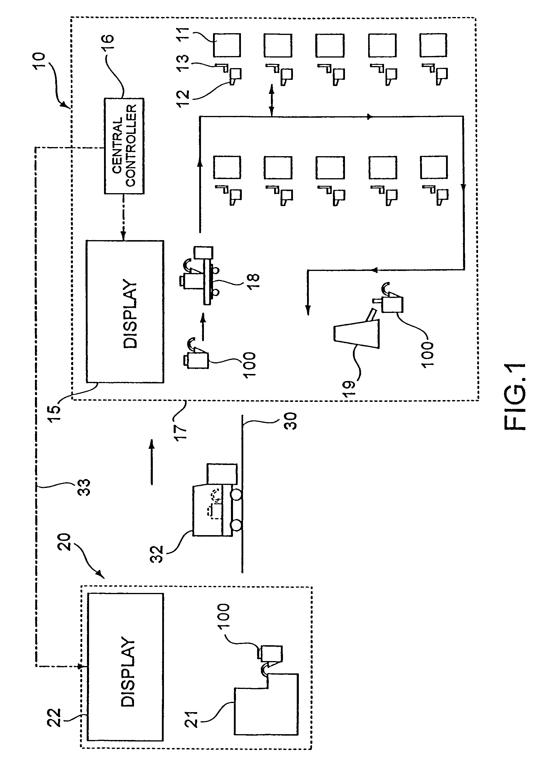
[0034]FIG. 1 is a schematic diagram showing the entire configuration of a metal supply system according to an embodiment of the present invention.

[0035]As shown in the drawing, a first factory 10 and a second factory 20 are provided at locations apart from each other across, for example, a public road 30.

[0036]In the first factory 10, a plurality of die-casting machines 11 are arranged as use points. Each of the die-casting machines 11 molds products in a desired shape by injection molding using molten aluminum as a raw material. The products can include, for example, parts relating to an engine of an automobile and the like. Besides, the molten metal is not limited only to an aluminum alloy, but alloys containing other metals such as magnesium, titanium, and so on as main constituents are also usable. Near the die-casting machines 11, there are storing furnaces (local storing fu...


PUM

PropertyMeasurementUnit
inner diameteraaaaaaaaaa

Abstract

A container does not need a member such as a stoke and the like that are exposed to the molten metal therein, thus the necessity to replace the parts such as the stoke and the like can be eliminated. In addition, there is no structure like the stoke in the container, the operability for the preheating is improved thus the preheating can be performed effectively. In addition, since a flow passage is formed inside the lining with high heat conductivity, inner heat of the container is easily conducted to the flow passage. Thus, the decrease in temperature of the molten metal that flows inside the flow passage can be suppressed to the utmost.

Description

TECHNICAL FIELD[0001]The present invention relates to a container used to transport, for example, molten aluminum.BACKGROUND ART[0002]In a factory where aluminum is molded using many die-casting machines, an aluminum material is often supplied not only from within the factory but also from outside the factory. In this case, a container storing aluminum in a melt is carried from a factory on the material supply side to a factory on the molding side to supply to each of the die-casting machines the material kept in the melt.DISCLOSURE OF THE INVENTION[0003]The present inventors propose a technique of supplying the molding material from such a container to the die-casting machine side utilizing a pressure difference. More specifically, this technique applies a pressure to the container to pour a molten material in the container to the outside through a pipe led to the container. As such a container, it is possible to use, for example, an apparatus disclosed in Japanese Patent Laid-Open...

Claims


Application Information

Patent Timeline
Patent Type & Authority Patents(United States)
IPC IPC(8): C21C5/42C21B7/12B67D7/02B22D41/05F27D1/00F27D3/00F27D3/12F27D3/14
CPCB22D41/05F27D1/00F27D3/123F27D3/14F27D2003/0054
Inventor MIZUNO, HITOSHIABE, TSUYOSHI
Owner HOEI SHOKAI CO LTD
Why Eureka
Try Eureka