
Cogeneration system

a cogeneration system and cogeneration technology, applied in vehicle heating/cooling devices, refrigeration machines, refrigeration components, etc., can solve the problem that the efficiency of cogeneration systems cannot be maximized, and achieve the effects of constant heating capacity, maximum energy efficiency, and enhancing the heating performance of heat pump type air conditioners

Inactive Publication Date: 2006-12-21
LG ELECTRONICS INC
View PDF7 Cites 71 Cited by
  • Summary
  • Abstract
  • Description
  • Claims
  • Application Information

AI Technical Summary

Benefits of technology

[0016] The present invention has been made in view of the above-mentioned problems, and it is an object of the invention to provide a cogeneration system in which waste heat of a drive source adapted to drive a generator can be used as a heat source for regenerating a dehumidifier to dehumidify air or as a heat source for heating indoor air, or can be used to enhance the heating performance of an air conditioner, so that the cogeneration system can obtain a maximal efficiency.
[0017] Another object of the invention is to provide a cogeneration system which can efficiently supply electric power generated from a generator and commercial electric power in accordance with an operation mode, namely, cooling or heating mode, an indoor operation load, and outdoor temperature.
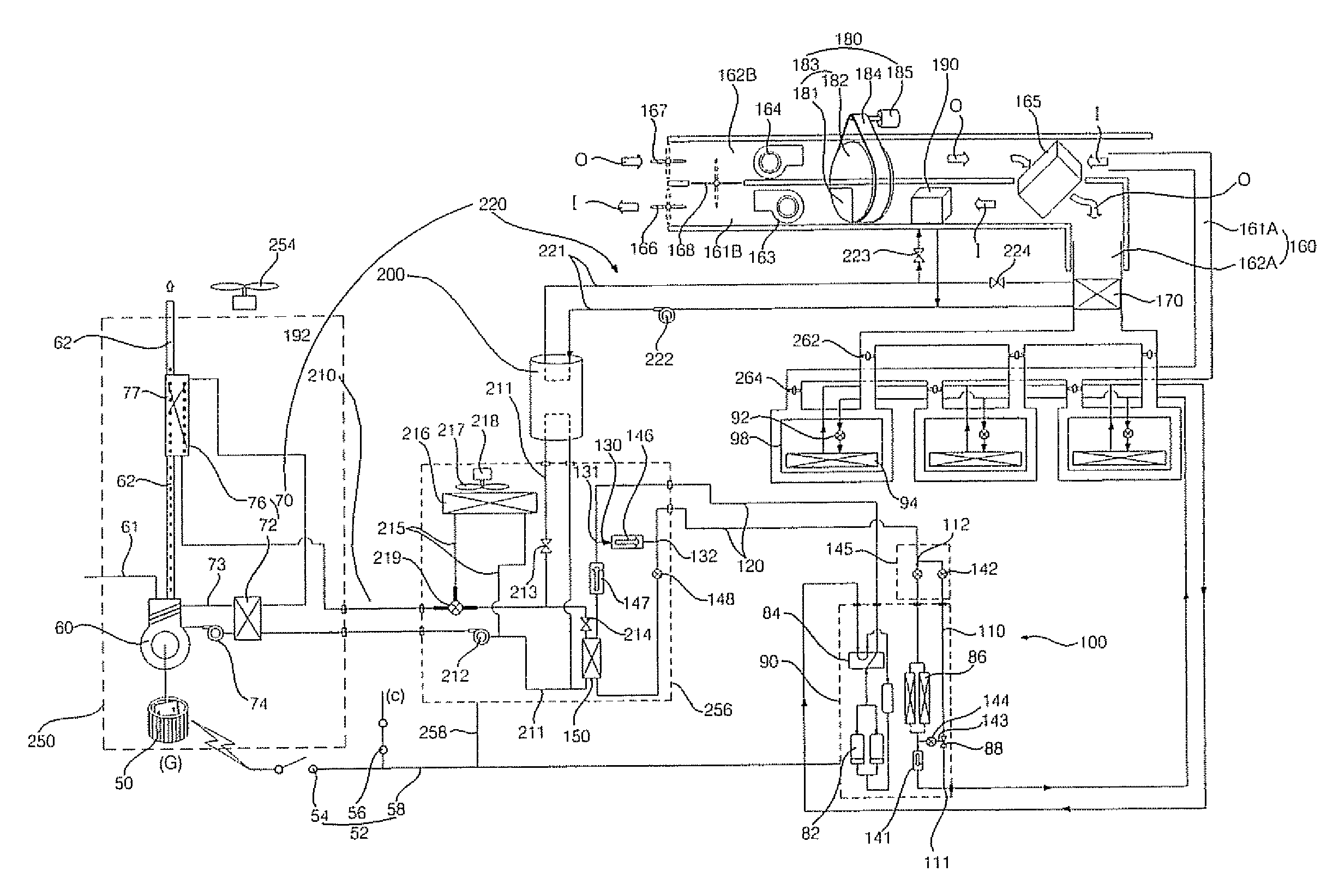
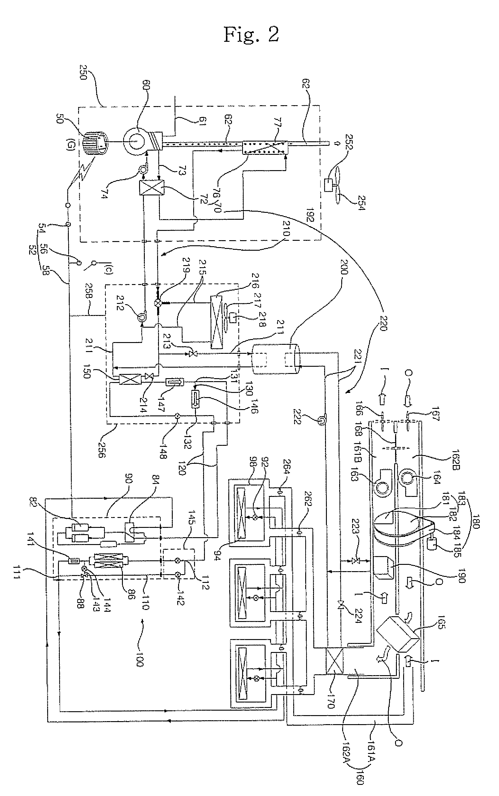
[0038] The cogeneration system according to the present invention can use the waste heat of the drive source for a variety of purposes depending on an indoor environment, and can therefore operate at a maximal energy efficiency because the the cogeneration system includes the generator, the drive source for driving the generator, the waste heat supplying heat exchanger for enhancing the heating performance of the heat pump type air conditioner, the auxiliary heating heat exchanger using the waste heat of the drive source as a heat source for heating indoor air, and the regeneration heat supplying heat exchanger using the waste heat of the drive source as a heat source for regenerating the dehumidifier.
[0039] Also, in the cogeneration system according to the present invention, when the heat pump type air conditioner operates in heating mode under the condition in which the outdoor temperature is low, the refrigerant is evaporated by the waste heat supplying heat exchanger which is heated by the waste heat. Accordingly, the heat pump type air conditioner can have a constant heating capacity irrespective of the outdoor temperature. It is also possible to minimize formation of frost on the outdoor heat exchangers.
[0040] Meanwhile, when the heat pump type air conditioner operates in cooling mode under the condition in which the operation load of the indoor units is high, the internally-generated electricity is supplied to the heat pump type air conditioner. On the other hand, when the operation load of the indoor units is low, the commercial electricity is supplied to the heat pump type air conditioner. Accordingly, it is possible to minimize the consumption of energy and the consumption of electricity during the cooling operation of the heat pump type air conditioner.

Problems solved by technology

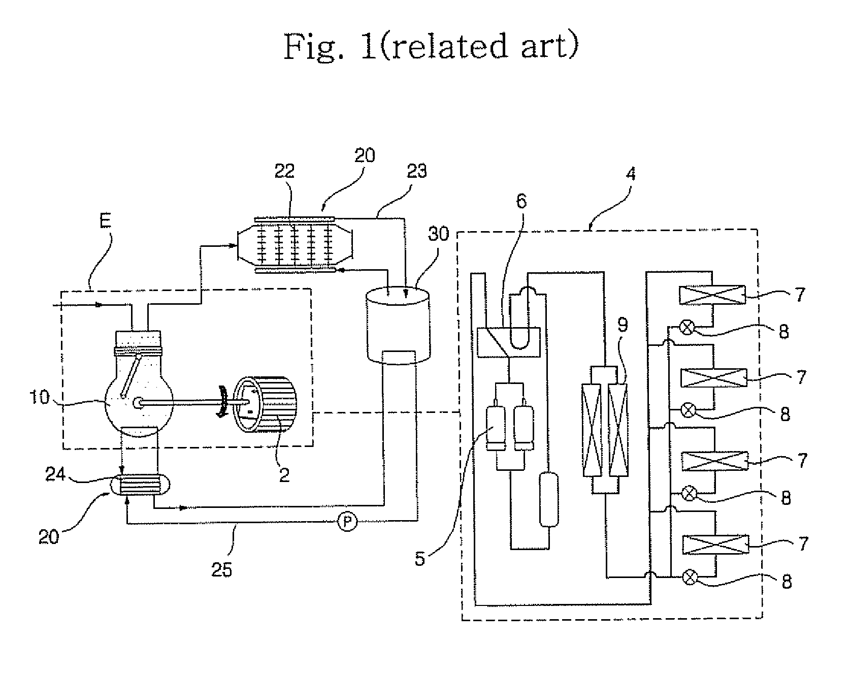
However, the conventional cogeneration system has a problem in that the efficiency of the cogeneration system cannot be maximized because the waste heat of the engine 10 is only used to supply hot water without being used in the heat pump type air conditioner 4.

Method used


Image

  • Cogeneration system
  • Cogeneration system
  • Cogeneration system

Examples


Embodiment Construction

[0048] Hereinafter, exemplary embodiments of a cogeneration system according to the present invention will be described with reference to the annexed drawings.

[0049]FIG. 2 is a schematic diagram of a cogenerarion system according to an exemplary embodiment of the present invention, illustrating a state in which the cogeneration system operates in cooling mode under a condition of a high indoor operation load. FIG. 3 is a schematic diagram of the cogeneration system according to the exemplary embodiment of the present invention, illustrating a state in which the cogeneration system operates in cooling mode under a condition of a low indoor operation load. FIG. 4 is a schematic diagram of the cogeneration system according to the exemplary embodiment of the present invention, illustrating a state in which the cogeneration system operates in heating mode under a condition of a low outdoor temperature. FIG, 5 is a schematic diagram of the cogeneration system according to the exemplary e...


PUM


Abstract

A cogeneration system is disclosed which includes a generator, a drive source for driving the generator, a waste heat supplying heat exchanger for enhancing the heating performance of a heat pump type air conditioner, an auxiliary heating heat exchanger using the waste heat of the drive source as a heat source for heating indoor air, and a regeneration heat supplying heat exchanger using the waste heat of the drive source as a heat source for regenerating a dehumidifier. The cogeneration system can use the waste heat of the drive source for diverse purposes in accordance with the indoor environment, and can have a maximal efficiency.

Description

BACKGROUND OF THE INVENTION [0001] 1. Field of the Invention [0002] The present invention relates to a cogeneration system, and, more particularly, to a cogeneration system in which waste heat of a drive source adapted to drive a generator can be used to enhance the heating performance of a heat pump type air conditioner, can be used as a heat source to regenerate a dehumidifier, and can be used to assist a heating operation of the heat pump type air conditioner. [0003] 2. Description of the Related Art [0004]FIG. 1 is a schematic view illustrating a conventional cogeneration system. [0005] As shown in FIG. 1, the conventional cogeneration system includes a generator 2 which generates electric power, a drive source 10 which operates to drive the generator 2, and generates waste heat during the operation thereof, such as an engine (hereinafter, the drive source 10 will be referred to as an “engine”), a waste heat recoverer 20 which recovers the waste heat generated from the engine 10...

Claims


Application Information

Patent Timeline
IPC IPC(8): B60H1/02
CPCF24F3/1423F24F12/006F24F2203/1016F24F2203/1032F24F2203/1056F24F2203/1068Y02B30/563F25B13/00F25B27/02F25B2313/0233F25B2341/0662Y02E20/14Y02B30/52F24F2203/1084F25B41/39Y02B30/56Y02A30/274F25B15/00F25B30/00
Inventor CHO, EUN JUNHA, SIM BOKCHUNG, BAIK YOUNGKIM, CHEOL MINCHANG, SE DONG
Owner LG ELECTRONICS INC
Learn More