Bobbin and loudspeaker using the same

a technology of bobbins and loudspeakers, applied in the field of bobbins and speakers, can solve the problems of difficult to improve the energy conversion efficiency of the loudspeaker, difficult to increase the rated power of the conventional loudspeaker, and audible distortion

Active Publication Date: 2013-04-16
TSINGHUA UNIV +1
View PDF68 Cites 0 Cited by
  • Summary
  • Abstract
  • Description
  • Claims
  • Application Information

AI Technical Summary

Benefits of technology

[0006]To evaluate the loudspeaker, sound volume is a decisive factor. The sound volume of the loudspeaker relates to the input power of the electric signals and the conversion efficiency of the energy (e.g., the conversion efficiency of the electrical to sound). The larger the input power, the larger the conversion efficiency of the energy, the bigger the sound volume of the loudspeaker. However, when the input power is increased to certain levels, the bobbin and diaphragm could deform or even break, thereby causing audible distortion. Therefore, the strength and tensile modulus of the elements in the loudspeaker are decisive factors of a rated power of the loudspeaker. The rated power is the highest input power by which the loudspeaker can produce sound without the audible distortion. Additionally, the lighter the weight of the elements in the loudspeaker, such as the weight of the bobbin and the weight per unit area of the diaphragm, the smaller the energy required for making the diaphragm vibrate, the higher the energy conversion efficiency of the loudspeaker, and the higher the sound volume produced by the same input power. Thus, the strength and the weight of the bobbin are important factors affecting the sound volume of the loudspeaker. The weight of the bobbin is related to a thickness and a density thereof. Accordingly, the higher the specific strength (e.g., strength-to-density ratio), the smaller the thickness of the bobbin of the loudspeaker, and the higher the sound volume of the loudspeaker.

Problems solved by technology

However, when the input power is increased to certain levels, the bobbin and diaphragm could deform or even break, thereby causing audible distortion.
The rated power of the conventional loudspeakers is difficult to increase partly due to the restriction of the conventional material of the bobbin.
Thus, it is difficult to improve the energy conversion efficiency of the loudspeaker.

Method used


Image

  • Bobbin and loudspeaker using the same
  • Bobbin and loudspeaker using the same
  • Bobbin and loudspeaker using the same

Examples


first embodiment

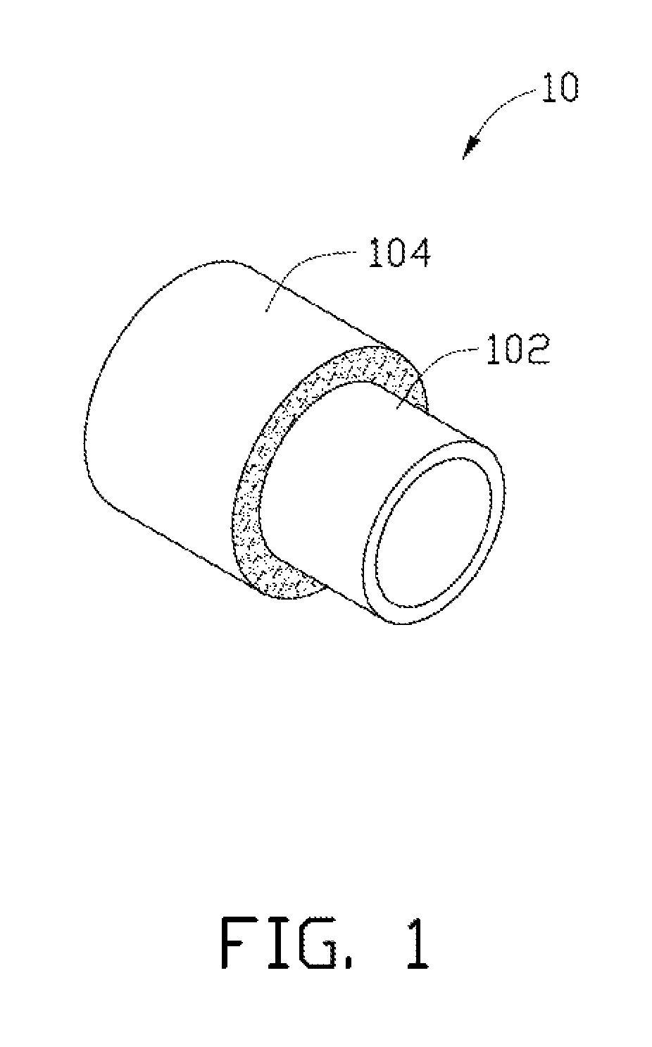
[0020]a bobbin 10 is illustrated in FIG. 1. The bobbin 10 has a hollow tubular structure. The bobbin 10 includes a base 102 and a carbon nanotube structure 104. The carbon nanotube structure 104 is deposited on at least one surface of the base 102. In one embodiment, the base 102 has a cylindrical configuration, and the carbon nanotube structure 104 wraps around an outer circumferential surface of the base 102. In another embodiment, the carbon nanotube structure 104 is disposed on an inner circumferential surface of the base 102.

[0021]The base 102 can be made of polyimide, polyester, aluminum, fiberglass, or paper. The base 102 can have a light weight and high specific strength. In one embodiment, the base 102 is a polyimide film. The polyimide film has a small density of about 1.35 g / cm3, thus, it is conducive to decrease the weight of the bobbin 10, and increase the specific strength thereof.

[0022]The carbon nanotube structure 104 can include at least one carbon nanotube film. Th...

second embodiment

[0040]The bobbin 10 adopting the carbon nanotube structure 104 can have a high specific strength and a lower weight because the carbon nanotube structure 104 has excellent mechanical strength and is lightweight. The increase of the specific strength can include increasing the strength of the bobbin while the density thereof is decreased, increasing the strength of the bobbin while the density thereof is increased, and decreasing the strength of the bobbin while the density thereof is decreased. a bobbin 20 is illustrated in FIG. 3. The bobbin 20 has a hollow tubular structure. The bobbin 20 includes a base 202 and a carbon nanotube structure 204. The carbon nanotube structure 204 is deposited on an outer circumferential surface of the base 202. The carbon nanotube structure 204 includes a carbon nanotube wire structure.

[0041]The compositions, features, and functions of the bobbin 20 in the embodiment shown in FIG. 3, are similar to the bobbin 10 in the first embodiment shown in FIG....

third embodiment

[0047]a bobbin 30 is illustrated in FIG. 4. The bobbin 30 has a hollow tubular structure. The bobbin 30 includes a base 302 and a carbon nanotube structure 304 deposited on at least one surface of the base 302. Specifically, the carbon nanotube structure 304 is located directly on at least one surface of the base 302. The carbon nanotube structure 304 includes a plurality of carbon nanotube wire structures.

[0048]The compositions, features, and functions of the bobbin 30 in the third embodiment shown in FIG. 4 are similar to the bobbin 20 in the second embodiment shown in FIG. 3, except that the present carbon nanotube structure 304 includes a plurality of carbon nanotube wire structures. The plurality of carbon nanotube wire structures can be substantially parallel to each other, crossed with each other, or woven together, and positioned on at least one surface of the base 302. Specifically, the plurality of carbon nanotube wire structures can be substantially parallel to each other...


PUM

PropertyMeasurementUnit
densityaaaaaaaaaa
diametersaaaaaaaaaa
diametersaaaaaaaaaa

Abstract

A bobbin for a loudspeaker includes at least one base and at least one carbon nanotube structure. The at least one carbon nanotube structure is positioned on at least one surface of the base. A loudspeaker includes a magnetic circuit, a bobbin; a voice coil, and a diaphragm. The magnetic circuit defines a magnetic gap. The bobbin is located in the magnetic gap and includes at least one carbon nanotube structure. The voice coil is wounded on the bobbin. The diaphragm includes an inner rim fixed to the bobbin.

Description

RELATED APPLICATIONS[0001]This application claims all benefits accruing under 35 U.S.C. §119 from China Patent Application No. 200910108180.4, filed on Jun. 26, 2009, in the China Intellectual Property Office, the contents of which are hereby incorporated by reference. This application is related to commonly-assigned application entitled, “BOBBIN AND LOUDSPEAKER USING THE SAME”, filed Jun. 28, 2010 12 / 824,371.BACKGROUND[0002]1. Technical Field[0003]The present disclosure relates to bobbins and speakers adopting the same.[0004]2. Description of Related Art[0005]A loudspeaker is an acoustic device transforming received electric signals into sounds. An electro-dynamic loudspeaker typically includes a diaphragm, a bobbin, a voice coil, a damper, a magnet, and a frame. The voice coil is an electrical conductor wrapped around the bobbin. The bobbin is connected to the diaphragm. The voice coil is placed in the magnetic field of the magnet.[0006]To evaluate the loudspeaker, sound volume is...

Claims


Application Information

Patent Timeline
Patent Type & Authority Patents(United States)
IPC IPC(8): H04R1/22H04R9/02H04R1/20H04R9/06
CPCB82Y30/00H04R9/046Y10T428/30Y10T428/13Y10T428/24132Y10T428/24058Y10T428/31678Y10T428/31993Y10T442/30
Inventor LIU, LIANGWANG, JIA-PING
Owner TSINGHUA UNIV
Why Eureka
Try Eureka