Cutting machine tool cutter mounting part structure

A technology for cutting machine tools and installation parts, which is applied in the direction of milling cutters, positioning devices, milling machine equipment, etc., can solve problems such as unsatisfactory requirements, and achieve the effects of high use precision, improved precision and rigidity, and long service life

Inactive Publication Date: 2018-06-29
张健
View PDF0 Cites 0 Cited by
  • Summary
  • Abstract
  • Description
  • Claims
  • Application Information

AI Technical Summary

Problems solved by technology

When the tool is longer, the cutting resistance is greater, and the precision requirements are higher, this split type tool holder tailstock cannot meet the demand

Method used


Image

  • Cutting machine tool cutter mounting part structure

Examples


Embodiment 1

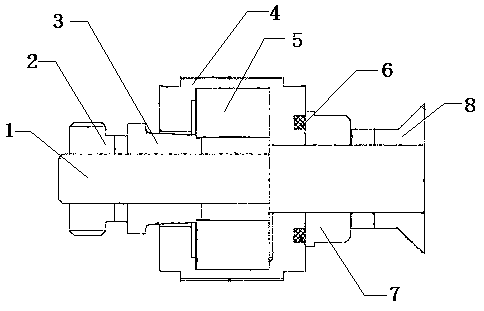
[0011] This embodiment provides a cutting machine tool mounting part structure, which is characterized in that: the cutting machine tool mounting part structure includes a tool bar (1), a rear locking part (2), a taper sleeve (3), a bearing sleeve (4 ), bearing part (5), sealing rubber ring (6), front locking part (7), tool installation part (8);

[0012] Among them: a bearing part (5) is arranged outside the cutter bar (1), a taper sleeve (3) is arranged between the bearing part (5) and the cutter bar (1), and a bearing sleeve (4) is arranged outside the bearing part (5) , the bearing part (5) is provided with front and rear locking parts (7, 2) at the front and rear of the cutter bar (1), and a sealing rubber ring is provided between the bearing sleeve (4) and the front and rear locking parts (7, 2) (6), the front end of the front locking part (7) of the tool bar (1) is provided with a tool mounting part (8).


PUM


Abstract

The invention discloses a cutting machine tool cutter mounting part structure. The cutting machine tool cutter mounting part structure is characterized by comprising a cutter bar, a rear locking part,a taper sleeve, a bearing sleeve, a bearing part, a sealing rubber ring, a front locking part and a cutter mounting part, wherein the bearing part is arranged outside the cutter bar, the taper sleeveis arranged between the bearing part and the cutter bar, the bearing sleeve is arranged outside the bearing part, the bearing part is provided with the front locking part at the front part of the cutter bar and the rear locking part at the rear part of the cutter bar, the front locking part and the rear locking part are used for locking, the sealing rubber ring is arranged between the bearing sleeve and the front locking part as well as the rear locking part, and the cutter mounting part is arranged at the front end of the front locking part of the cutter bar. The cutting machine tool cuttermounting part structure has the advantages that a cutter bar tailstock clamped by the taper sleeve is adopted, an integrated structure is achieved, and the precise elastic taper sleeve is adopted at the part between the cutter bar and a bearing inner ring to realize clearance-free clamping, so that the precision and the rigidity of the cutter bar are greatly improved, the advantages of being highin rigidity, high in precision, and high in rotating speed are achieved, the using precision is higher, and the service life is longer.

Description

technical field [0001] The invention relates to a tool bar tailstock clamped by a precision elastic cone sleeve, and in particular provides a tool mounting part structure of a cutting machine tool. Background technique [0002] In some cutting machine tools for hobbing and milling, hobs and milling cutters are installed on the cutter bar for rotary cutting. The front end of the tool bar is connected to the tool spindle of the machine tool to obtain the force required for cutting and the accuracy and stiffness. If the cutter is short, the motion accuracy and rigidity of the cantilever beam installation of the cutter rod can generally meet the processing requirements, but if the cutter is long, the motion accuracy and rigidity of the cutter rod tailstock are relatively low under the action of cutting resistance. The front end is descending geometrically, which obviously cannot meet the requirements of processing operations. During the processing of the tool, it needs to be r...

Claims


Application Information

Patent Timeline
IPC IPC(8): B23C5/26B23Q3/12
CPCB23C5/26B23Q3/12
Inventor 张健
Owner 张健
Why Eureka
Try Eureka