Automobile maintenance tool and using method thereof

A vehicle maintenance and tool technology, applied in vehicle maintenance/repair, manufacturing tools, workbenches, etc., can solve the problems of inconvenient operation, manual adjustment, and inconvenient lateral displacement of the flip frame, and achieves improved efficiency, good maintenance, and good lighting effect

Pending Publication Date: 2018-06-29
唐朝
View PDF2 Cites 1 Cited by
  • Summary
  • Abstract
  • Description
  • Claims
  • Application Information

AI Technical Summary

Problems solved by technology

[0006] Both of the above two reversing frames can realize the necessary rotation of the engine, but they still have some disadvantages, such as the fixed direction of rotation, the lateral displacement of the reversing frame is not very convenient, manual adjustment is required, etc., resulting in inconvenient operation

Method used


Image

  • Automobile maintenance tool and using method thereof
  • Automobile maintenance tool and using method thereof
  • Automobile maintenance tool and using method thereof

Examples


Embodiment 1

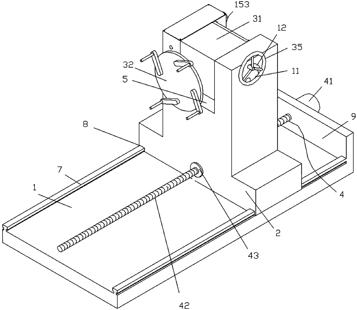
[0032] Such as Figure 1 to Figure 4 As shown, an automobile maintenance tool includes an overturning frame 3, a support 2 and a base 1. The top of the support 2 is provided with a notch 5, and two ends of the overturning frame 3 are connected with a rotating shaft 6 and rotating through the rotating shaft 6. Connected in the gap 5, the rotating shaft 6 is also connected with a rotating mechanism 15 for driving the turning frame 3 to rotate in a vertical plane, the base 1 is provided with a slide rail 7, and the cross section of the slide rail 7 is "T" The bottom of the support 2 is provided with a sliding groove 8 that is matched with the slide rail 7, a positioning plate 9 is provided at one end of the base 1, and a lateral movement mechanism 4 is installed on the positioning plate 9. The support 2 and the lateral movement The mechanism 4 is connected and can move back and forth on the slide rail 7.

[0033] In this embodiment, the turning frame 3 includes a turning box 31, a ...

Embodiment 2

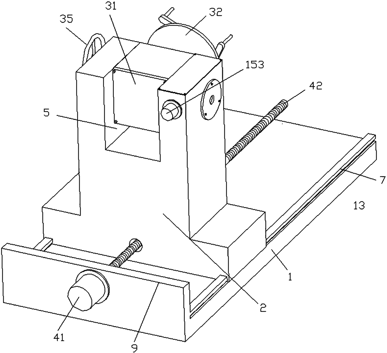
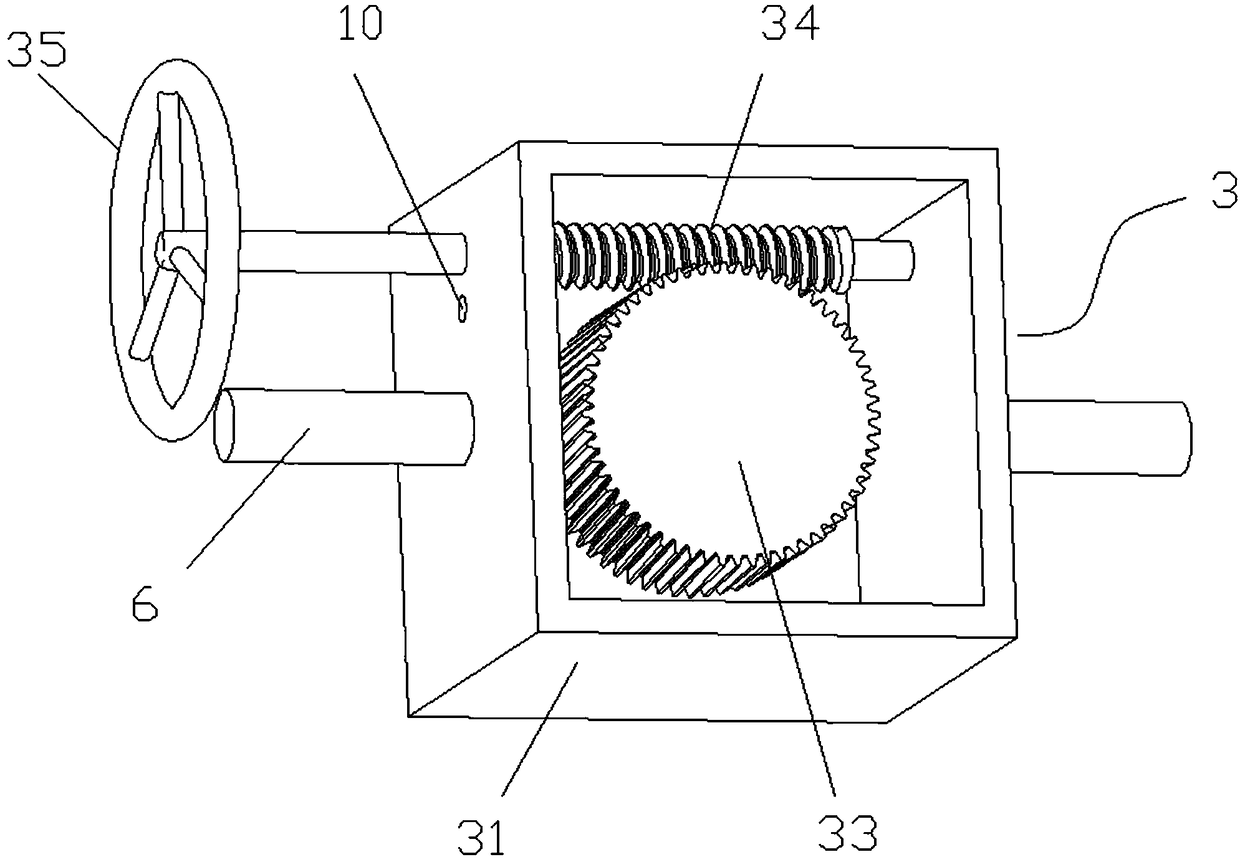
[0040] Such as Figure 5 with Image 6 As shown, an automobile maintenance tool includes an overturning frame 3, a support 2 and a base 1. The top of the support 2 is provided with a notch 5, and two ends of the overturning frame 3 are connected with a rotating shaft 6 and rotating through the rotating shaft 6. Connected in the gap 5, the rotating shaft 6 is also connected with a rotating mechanism 15 for driving the turning frame 3 to rotate in a vertical plane, the base 1 is provided with a slide rail 7, and the cross section of the slide rail 7 is "T" The bottom of the support 2 is provided with a sliding groove 8 that is matched with the slide rail 7, a positioning plate 9 is provided at one end of the base 1, and a lateral movement mechanism 4 is installed on the positioning plate 9. The support 2 and the lateral movement The mechanism 4 is connected and can move back and forth on the slide rail 7.

[0041] In this embodiment, the turning frame 3 includes a turning box 31, a...


PUM


Abstract

The invention discloses an automobile maintenance tool and relates to the field of automobile maintenance equipment. The automobile maintenance tool comprises a roll-over stand, a support and a base.The top of the support is provided with a gap, the two ends of the roll-over stand are connected with rotating shafts and rotationally connected into the gap through the rotating shafts, the rotatingshafts are further connected with a rotating mechanism used for driving the roller-over stand to be rotated in the vertical plane, the base is provided with a sliding rail, the bottom of the support is provided with a sliding groove matched with the sliding rail, one end of the base is provided with a positioning plate, the positioning plate is provided with a transverse moving mechanism, and thesupport is connected with the transverse moving mechanism and can move back and forth on the sliding rail. By means of a turbine worm structure, rotary operation of an engine in multiple directions can be achieved, the maintenance efficiency is improved, meanwhile, transverse movement of the support on the sliding rail can be achieved through the adopted transverse moving mechanism, maintenance space can be adjusted, and engines with different types and sizes can be conveniently maintained.

Description

Technical field [0001] The invention belongs to the field of auto repair equipment, and in particular relates to an auto repair tool and a use method of the auto repair tool. Background technique [0002] Since the engine can provide sufficient power in different environments and is widely used, the need for maintenance of the engine is also greater. Therefore, auxiliary engine maintenance equipment has become the focus of current research. [0003] Traditional engine maintenance uses multiple maintenance auxiliary equipment to complete the maintenance of an engine, and the turning process is complicated, which wastes a lot of manpower and financial resources, and this combination of multiple maintenance auxiliary equipment causes inconvenient movement of the maintenance auxiliary equipment, and there are also engine problems. Different types of maintenance equipment require different auxiliary equipment, resulting in a large number of maintenance auxiliary equipment required for e...

Claims


Application Information

Patent Timeline
Patent Type & Authority Applications(China)
IPC IPC(8): B25H1/10B60S5/00
CPCB25H1/10B60S5/00
Inventor 唐朝
Owner 唐朝
Why Eureka
Try Eureka