Multi-degree-of-freedom driving device, mechanical arm and robot

A driving device and degree-of-freedom technology, applied in the field of mechanical arms, robots, and multi-degree-of-freedom driving devices, can solve the problems of high maintenance cost, single function, and low overall performance of the robot, and achieve the effect of compact structure and flexible movement.

Active Publication Date: 2018-06-29
刘坚坚
View PDF9 Cites 1 Cited by
  • Summary
  • Abstract
  • Description
  • Claims
  • Application Information

AI Technical Summary

Problems solved by technology

[0002] At present, most robots at home and abroad are driven by motors. The motors take up a lot of space and have a single function. The maintenance cost is high, which further causes the overall performance of the robot to be low.

Method used


Image

  • Multi-degree-of-freedom driving device, mechanical arm and robot
  • Multi-degree-of-freedom driving device, mechanical arm and robot
  • Multi-degree-of-freedom driving device, mechanical arm and robot

Examples


Embodiment 1

[0045] This embodiment is used for two-degree-of-freedom motions similar to human body's knee joint and elbow joint.

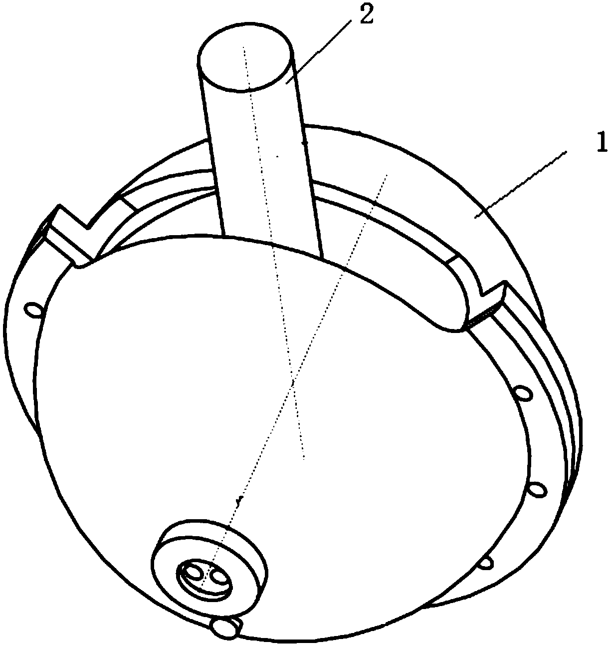
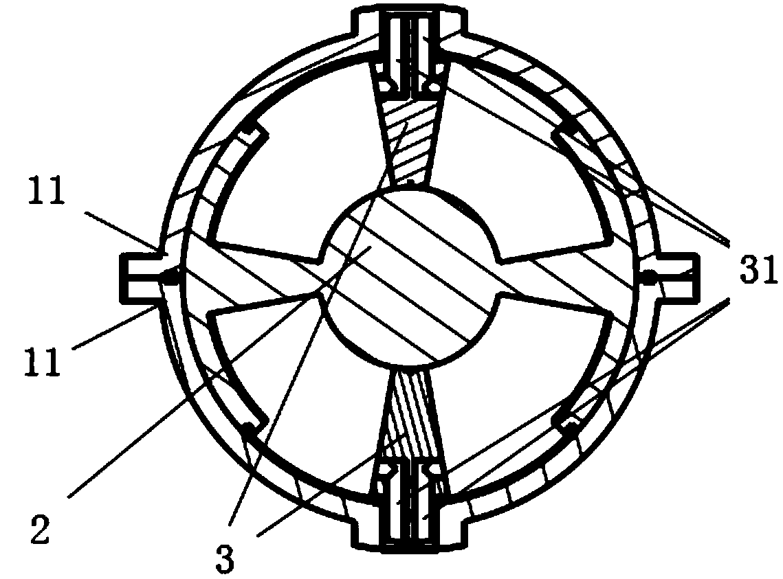
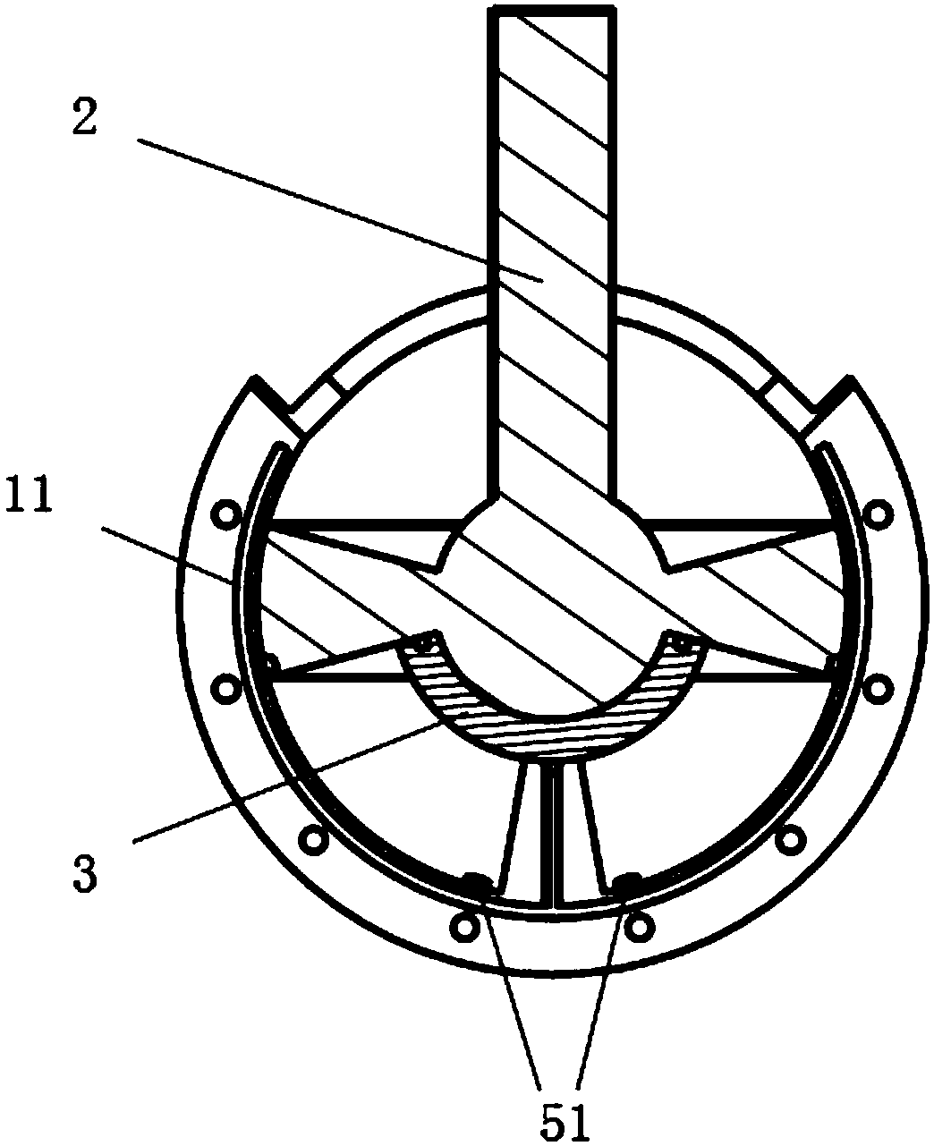
[0046] Such as Figure 1~6c As shown, a multi-degree-of-freedom driving device includes: a housing 1; an output member 2, one end of the output member is set as a spherical surface and is arranged in the housing 1, and the other end is extended outside the housing 1; a pair of first Limiting block 3, which is symmetrically arranged on both sides of the spherical surface of the output member 2, one end of the first limiting block 3 is in contact with the spherical surface of the output member 2, and the other end is rotatably connected to the housing 1; the output A number of oil cavities are formed between the member 2 and the housing 1 to control the oil pressure difference in different oil cavities, so that the output member swings or rotates around its own axis.

[0047] Said casing 1 includes a pair of housings 11 arranged opposite to each other, specific...

Embodiment 2

[0057]This embodiment is used for wrist joint movement similar to that of a human body.

[0058] see Figure 7~12c , as a modified structure of Embodiment 1, this embodiment also provides a multi-degree-of-freedom driving device, which includes: a housing 1, an output member 2, a pair of first limit blocks 3, and a pair of second Gasket 8, one end of the output member is arranged in the housing 1, wherein the connection relationship between the housing 1, the output member 2 and the pair of first limit blocks 3 is the same as in the above embodiment, and the pair of second gaskets 8 is in contact between the output member 2 and the housing 1 .

[0059] Two first oil chambers are formed between the output member 2 and the second gasket 8 and the housing 1, and the oil pressure difference in the two groups of oil chambers is controlled so that the output member surrounds the first limit The axis between the blocks 3 moves, and the range of motion of the output member 2 in this...


PUM


Abstract

The invention discloses a multi-degree-of-freedom driving device, a mechanical arm and a robot. The multi-degree-of-freedom driving device comprises a shell, an output component and a pair of first limiting blocks; one end of the output component is designed to be a spherical surface and is arranged in the shell, and the other end of the output component extends out of the shell; the first limiting blocks are symmetrically arranged on two sides of the spherical surface of the output component; one end surface of each first limiting block is in contact with the spherical surface of the output component, and the other end surface of each first limiting block is rotatably connected with the shell; and a plurality of oil cavities are formed between the output component and the shell to controloil pressure differences in the different oil cavities, so that the output component swings or rotates around the own axis of the output component.

Description

technical field [0001] The invention relates to a driving device, in particular to a multi-freedom driving device, a mechanical arm and a robot. Background technique [0002] At present, most robots at home and abroad are driven by motors, which take up a lot of space and have a single function and high maintenance costs, which further cause the overall performance of the robot to be low. Contents of the invention [0003] In view of this, the object of the present invention is to provide a multi-degree-of-freedom drive device, a mechanical arm and a robot, which adopt hydraulic drive to make the robot mechanism compact and maneuverable. [0004] In order to achieve the above object, the present invention is achieved through the following technical solutions: [0005] A multi-degree-of-freedom driving device is characterized in that it includes: [0006] shell; [0007] An output member, one end of the output member is set as a spherical surface and arranged inside the ...

Claims


Application Information

Patent Timeline
Patent Type & Authority Applications(China)
IPC IPC(8): B25J17/02
CPCB25J17/0258
Inventor 刘坚坚
Owner 刘坚坚
Why Eureka
Try Eureka