Autonomous propulsion type soft robot main body

A robotic and propulsive technology, applied in the field of medical devices, can solve the problems of patients' cavity scratches, perforations, and increased safety hazards, and achieve the effect of improving human comfort and operational safety.

Active Publication Date: 2018-10-16
TSINGHUA UNIV
View PDF6 Cites 13 Cited by
  • Summary
  • Abstract
  • Description
  • Claims
  • Application Information

AI Technical Summary

Problems solved by technology

[0004] However, the above-mentioned embedded wires and rigid fixing joints will add many safety hazards to the operation process. If the operation is improper, it will cause very serious injuries such as scratches and perforations to the patient's cavity.

Method used


Image

  • Autonomous propulsion type soft robot main body
  • Autonomous propulsion type soft robot main body
  • Autonomous propulsion type soft robot main body

Examples


Embodiment 1

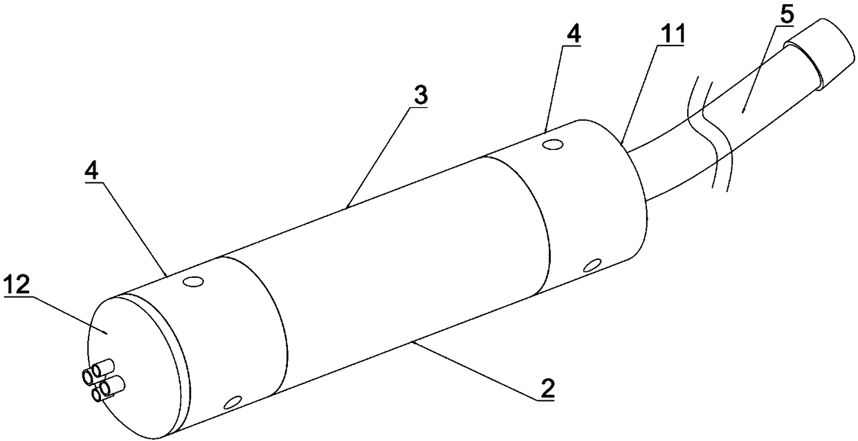
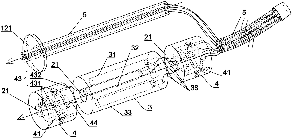
[0055] This embodiment provides a soft robot main body, its structure is as follows: Figure 1 to Figure 11 As shown, it is suitable for automatic walking in the cavity, which includes a tube body 2, a propulsion structure 3, and a support structure 4. The inside of the tube body 2 is provided with a tube body cavity 21 along the axial direction, such as figure 2 The propulsion structure 3 shown includes a first drive unit 31 , a second drive unit 32 and a third drive unit 33 that are uniformly fixed on the peripheral wall of the tube body cavity 21 relative to the axis of the tube body cavity 21 along the axial direction of the tube body 2 , The first driving unit 31 , the second driving unit 32 and the third driving unit 33 can be extended or contracted along the axial direction of the pipe body 2 . Such as Figure 8 As shown, when the second driving unit 32 and the third driving unit 33 distributed uniformly in the axial direction in the tubular body 2 are respectively ex...

Embodiment 2

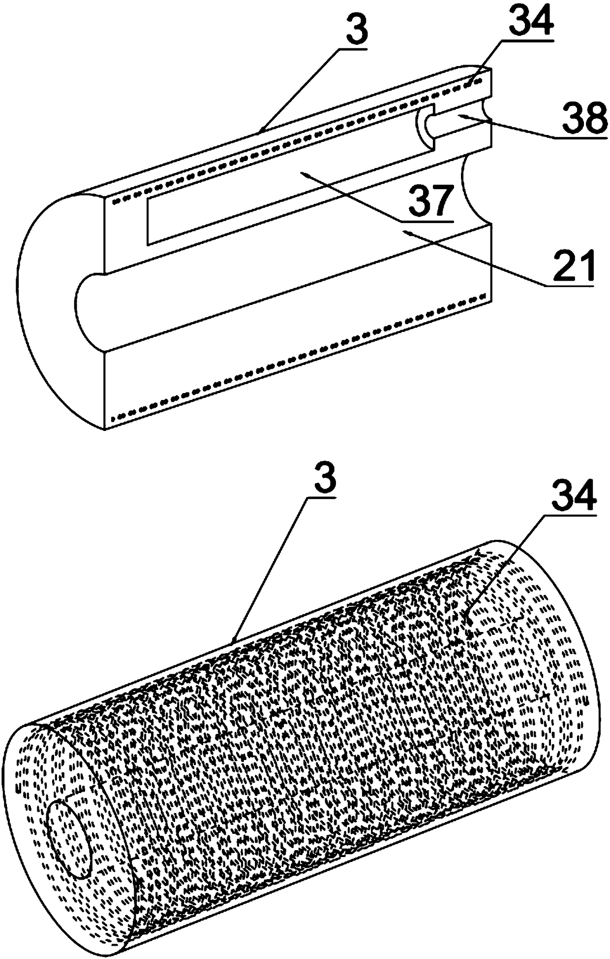
[0085] This embodiment provides a main body of an autonomously propelled soft robot. The difference between it and Embodiment 1 is that the first constraining layer 34 in this embodiment is along the first driving unit 31, the second driving unit 32 and the third driving unit respectively. 33 surrounds the outside of the first drive unit 31, the second drive unit 32 and the third drive unit 33, and is suitable for defining the first drive unit 31, the second drive unit 32 and the third drive unit 33 along the pipe body 2. Axial elongation or contraction. Such as Figure 11 As shown, the first constraining layer 34 is respectively wrapped on the outside of the drive unit, so that the confinement effect on each drive unit is more precise. At the same time, the first constraining layer 34 of different winding methods can also be configured for each drive unit, so that the propulsion The combination of various actions such as elongation, shortening or twisting of the structure 3 ...

Embodiment 3

[0087] Such as Figure 13 As shown, the present embodiment provides a self-propelled soft robot main body, which is different from the main propulsion soft robot main body in Embodiment 1 in that the first drive unit 31, the second drive unit 32 and the third drive unit 33 Each has a first expansion body 35 , and a first fluid accommodating cavity 37 is formed in the first expansion body 35 . Specifically, such as Figure 12 As shown, three expansion cavities 36 are evenly opened on the peripheral wall of the tubular body 2 along the circumferential direction, and three first expansion bodies 35 are placed in each expansion cavity 36 respectively, and the shape of each first expansion body 35 is similar to that of the expansion cavity 36 By matching, the first driving unit 31 , the second driving unit 32 and the third driving unit 33 are formed. A first fluid accommodating chamber 37 is opened inside each first expansion body 35 , and one end of the first fluid accommodating...


PUM


Abstract

The invention provides an autonomous propulsion type soft robot main body, which comprises a pipe body, wherein the inner part of the pipe body is provided with, in the axial direction, a pipe body cavity and: at least one propulsion structure, wherein the at least one propulsion structure includes a first driving unit, a second driving unit and a third driving unit which are fixedly and uniformlyarranged on the peripheral wall of the pipe body cavity in the axial direction of the pipe body and relative to the axial center of the pipe body cavity, the first driving unit, the second driving unit and the third driving unit can respectively extend or contract in the axial direction of the pipe body; at least two supporting structures, wherein at least one propulsion structure is arranged between every two adjacent supporting structures, the supporting structures are fixedly connected with the propulsion structures and are arranged on the outer peripheral wall of the pipe body cavity, andis used for fixing at least one end of the main body of the autonomous propulsion type soft robot on the cavity, thereby providing support for the main body of the autonomous propulsion type soft robot. The autonomous propulsion type soft robot main body can reduce the harm to the human body cavity and reduce the operation risk.

Description

technical field [0001] The invention relates to the technical field of medical devices, in particular to a main body of an autonomously propelled soft robot. Background technique [0002] At present, the insertion part of a medical endoscope is relatively hard compared to human tissue, and the main method of inserting it into a body cavity is to apply force outside the patient's body. [0003] The patent document whose publication number is CN103006165A provides a flexible endoscopic robot with variable stiffness, which has a catheter part, a driving part, a fluid supply part and a balloon part, and one end of the catheter part is connected with the driving part to complete the catheter part Propulsion; the fluid supply part is connected with the balloon part through the fluid tube, and the support for the catheter part in the cavity is realized by controlling the expansion degree of the balloon part. The catheter part is embedded with a wire rope and a hard fixed joint, th...

Claims


Application Information

Patent Timeline
Patent Type & Authority Applications(China)
IPC IPC(8): A61B1/005A61B1/00
CPCA61B1/00071A61B1/00105A61B1/00119A61B1/0051A61B1/0055A61B1/0057B25J9/065A61B1/00133A61B1/00156A61B1/00057A61B1/015
Inventor 廖洪恩张博语王鹤翔张天天
Owner TSINGHUA UNIV
Why Eureka
Try Eureka