
Flow state adjusting structure and method for three-ditch water flow same-direction Orbal oxidation ditch

A technology for flow regulation and oxidation ditch, which is applied in chemical instruments and methods, biological water/sewage treatment, water/sludge/sewage treatment, etc. It can solve the problem of anisotropic water flow direction in the corridors in anoxic areas and the inability to achieve variable-speed flow. In order to achieve the effect of reducing the apparent flow rate and increasing the apparent flow rate of the flow in the aeration zone

Active Publication Date: 2018-06-29
SHAANXI UNIV OF SCI & TECH
View PDF9 Cites 0 Cited by
  • Summary
  • Abstract
  • Description
  • Claims
  • Application Information

AI Technical Summary

Problems solved by technology

However, the implementation of this process requires that the oxidation ditch process must have an independent anoxic zone corridor, that is, this technology is only applicable to the Carrousel oxidation ditch process with more than three corridors, and the water flow direction of the anoxic zone corridor must be in the opposite direction.
For the Orbal oxidation ditch process, due to the shape of the pool, the Orbal oxidation ditch process does not have a corridor that is completely anoxic, and generally the direction of water flow in the three corridors of the Orbal oxidation ditch process is the same, so variable-speed flow regime adjustment cannot be achieved

Method used


Image

  • Flow state adjusting structure and method for three-ditch water flow same-direction Orbal oxidation ditch

Examples


Embodiment Construction

[0017] The present invention will be described in detail below with reference to the accompanying drawings and examples.

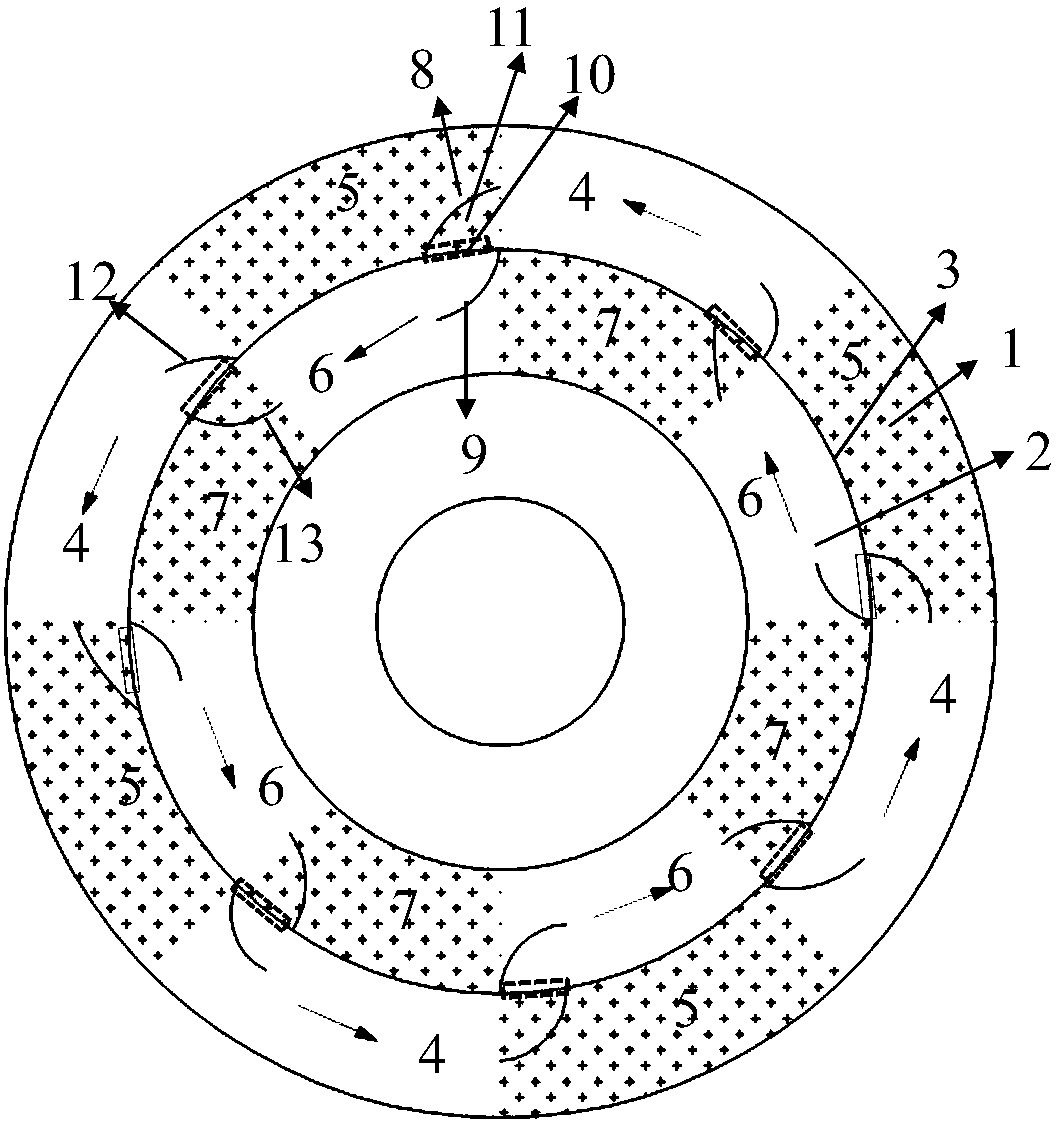
[0018] Such as figure 1 As shown, firstly keep the direction of the mixed liquid flow in the outer ditch 1 and the middle ditch 2 of the Orbal oxidation ditch in the same direction, and arrange the microporous aeration zones alternately in the outer ditch 1 of the Orbal oxidation ditch and the middle ditch 2 of the oxidation ditch to aerate the outer ditch Zone 5 and the anoxic zone 6 of the middle ditch are within a fan-shaped range with the same point as the center, and the anoxic zone 4 of the outer ditch and the aeration zone 7 of the middle ditch are within the fan-shaped range with the same point as the center. Then open holes 10 on the partition wall 3 between the outer ditch 1 of the oxidation ditch and the middle ditch 2 of the oxidation ditch. From the junction of area 6, it is opened downstream along the direction of water flow. An outer water ...


PUM


Abstract

The invention provides a flow state adjusting structure and method for a three-ditch water flow same-direction Orbal oxidation ditch. The flow state adjusting structure comprises an oxidation ditch middle ditch and an oxidation ditch outer ditch, which are arranged at the outer side of the oxidation ditch; each of the oxidation ditch middle ditch and the oxidation ditch outer ditch is provided with an aeration zone and an anoxic zone at interval; a separation wall is arranged between the oxidation ditch middle ditch and the oxidation ditch outer ditch; a hole with a certain width is formed inthe downstream of a crossed part of the aeration zone and the anoxic zone on the separation wall along a water flow direction; raw water firstly enters the outer ditch anoxic zone of the oxidation ditch; then water flow flows through the crossed part of the outer ditch anoxic zone and the outer ditch aeration zone; part of the water flow flows out from the hole, and a flow guide wall in the anoxiczone is used for smoothly guiding the water flow flowing out from the hole into the middle ditch anoxic zone in the downstream; the water flow flows into the middle ditch anoxic zone from the outer ditch anoxic zone in an unchanged direction; the water flow flows toward the downstream in the middle ditch anoxic zone; part of the water flow enters the next outer ditch anoxic zone of the outer ditch again through the hole under the action of an outer flow guide wall and an inner water distribution wall and continually flows toward the downstream. The flow state adjusting structure and method, provided by the invention, have the characteristic of realizing speed change and energy saving of the oxidation ditch.

Description

technical field [0001] The invention relates to the technical field of sewage treatment, in particular to a three-ditch water flow co-direction Orbal oxidation ditch flow state regulation structure and method. Background technique [0002] The oxidation ditch process is a common sewage treatment process. The traditional oxidation ditch process uses surface aeration equipment. The surface aeration equipment plays the role of oxygenation, pushing and stirring. In order to ensure that the activated sludge in the oxidation ditch system is in a suspended state, The flow rate of the oxidation ditch process is generally controlled above 0.3m / s. In order to improve the aeration efficiency of the system and reduce the energy consumption of operation, the microporous aeration system has gradually been popularized and applied in the oxidation ditch process in recent years. Due to the gas mixing and lifting effect of the microporous aerator arranged at the bottom of the tank, the micro...

Claims


Application Information

Patent Timeline
IPC IPC(8): C02F3/12C02F3/30
CPCC02F3/1257C02F3/301Y02W10/10
Inventor 王先宝张安龙
Owner SHAANXI UNIV OF SCI & TECH
Learn More