
A new combined oil and gas recovery system and oil and gas recovery method

An oil and gas recovery system and combined technology, applied in the direction of liquid hydrocarbon mixture recovery, separation methods, chemical instruments and methods, etc., can solve the problems of not meeting the use requirements, poor desorption effect, endangering safety production, etc., and achieve enhanced heat conduction The effect of improving desorption efficiency and improving work efficiency

Active Publication Date: 2022-05-06
中国人民解放军军事科学院国防工程研究院工程防护研究所
View PDF0 Cites 0 Cited by
  • Summary
  • Abstract
  • Description
  • Claims
  • Application Information

AI Technical Summary

Problems solved by technology

[0002] With the development of economy and industry, the consumption of gasoline, diesel and other fuels is constantly increasing rapidly, and the fuel is highly volatile, and it is inevitable that oil and gas will be generated during the tank farm, tanker loading, unloading, and fuel use. Oil and gas treatment Improper chemical smog will be discharged into the atmosphere, endangering safe production and polluting the environment. At the same time, the discharge of oil and gas must meet the emission standards stipulated by the state, so oil and gas must be recovered
The traditional tank body used for oil and gas recovery adopts the bottom-in and top-out method, and the desorption gas enters the desorption tank from one inlet for desorption, but the desorption effect is not good when vacuuming and desorbing from one port, and the desorption time is relatively long , the desorption efficiency is low, and the use requirements cannot be met

Method used


Image

  • A new combined oil and gas recovery system and oil and gas recovery method
  • A new combined oil and gas recovery system and oil and gas recovery method
  • A new combined oil and gas recovery system and oil and gas recovery method

Examples


Embodiment Construction

[0028] The specific implementation of the present invention will be further described in detail below in conjunction with the accompanying drawings. The accompanying drawings of the present invention are only for exemplary illustrations and cannot be understood as limitations to the present invention. In order to better illustrate the following embodiments, some parts of the accompanying drawings will have The omission, enlargement or reduction does not represent the size of the actual product; for those skilled in the art, it is understandable that some well-known structures and their descriptions in the drawings may be omitted.

[0029] The connections described in the following examples all refer to connections through pipelines, and the desorption gas is nitrogen.

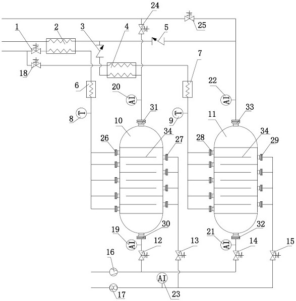
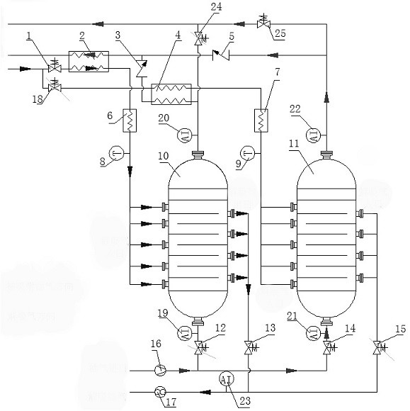
[0030] Such as figure 1 , figure 2 As shown, a new combined oil and gas recovery system and oil and gas recovery method, the oil and gas recovery system includes oil and gas adsorption / desorption module I, oi...


PUM


Abstract

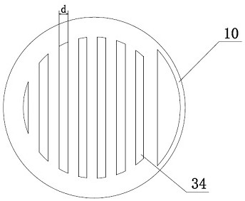
A new combined oil and gas recovery system and oil and gas recovery method, the oil and gas recovery system includes oil and gas adsorption / desorption module I, oil and gas adsorption / desorption module II, oil and gas inlet pipeline, desorption gas inlet pipeline, desorption oil and gas discharge pipe The oil and gas adsorption / desorption module I and the oil and gas adsorption / desorption module II have the same structure, including tanks, desorption inlets, desorption outlets, oil and gas inlets, and exhaust gas outlets; the oil and gas inlet pipelines It is equipped with a fan, a solenoid valve and an oil and gas concentration meter connected in sequence. The new combined oil and gas recovery method uses horizontally opposite desorption inlets and desorption outlets evenly distributed on the side of the tank body, so that the desorption airflow in the horizontal direction is evenly distributed, ensuring that the adsorbent is evenly heated and improving the desorption efficiency. The oil and gas adsorption / desorption module I, The oil and gas adsorption / desorption module II switches between the adsorption and desorption working modes under the action of the control module to realize continuous non-stop operation of oil and gas recovery.

Description

technical field [0001] The invention belongs to the technical field of oil and gas recovery, and in particular relates to a novel combined oil and gas recovery system and an oil and gas recovery method. Background technique [0002] With the development of economy and industry, the consumption of gasoline, diesel and other fuels is constantly increasing rapidly, and the fuel is highly volatile, and it is inevitable that oil and gas will be generated during the tank farm, tanker loading, unloading, and fuel use. Oil and gas treatment Improper chemical smog will be formed and discharged into the atmosphere, endangering safe production and polluting the environment. At the same time, the discharge of oil and gas must meet the emission standards stipulated by the state, so oil and gas must be recovered. The traditional tank body used for oil and gas recovery adopts the bottom-in and top-out method, and the desorption gas enters the desorption tank from one inlet for desorption, ...

Claims


Application Information

Patent Timeline
Patent Type & Authority Patents(China)
IPC IPC(8): C10G5/02B01D53/04
CPCC10G5/02B01D53/04B01D53/0454B01D2259/4009
Inventor 汪剑辉陈叶青薛恒吕林梅陈经赵强朱新华
Owner 中国人民解放军军事科学院国防工程研究院工程防护研究所
Learn More